Position sensor based on capacity

A sensor, capacitor technology, used in the field of capacitance-based position sensors

Inactive Publication Date: 2004-05-19
HEWLETT PACKARD CO
View PDF2 Cites 18 Cited by
  • Summary
  • Abstract
  • Description
  • Claims
  • Application Information

AI Technical Summary

Problems solved by technology

Many existing sensors are simply not sensitive enough to provide an output suitable for determining such fine positional resolution

Method used


Image

  • Position sensor based on capacity
  • Position sensor based on capacity
  • Position sensor based on capacity

Examples


Embodiment Construction

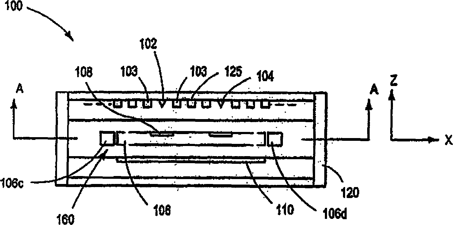
[0017] The present invention is directed to a capacitance based position sensor. The position sensor embodiments described herein may be used in a wide variety of devices, but have proven particularly suitable for use in very small computer storage devices and other MEMS systems. For purposes of illustration only, the described position sensor embodiments are discussed below primarily in the context of high density MEMS computer storage devices.

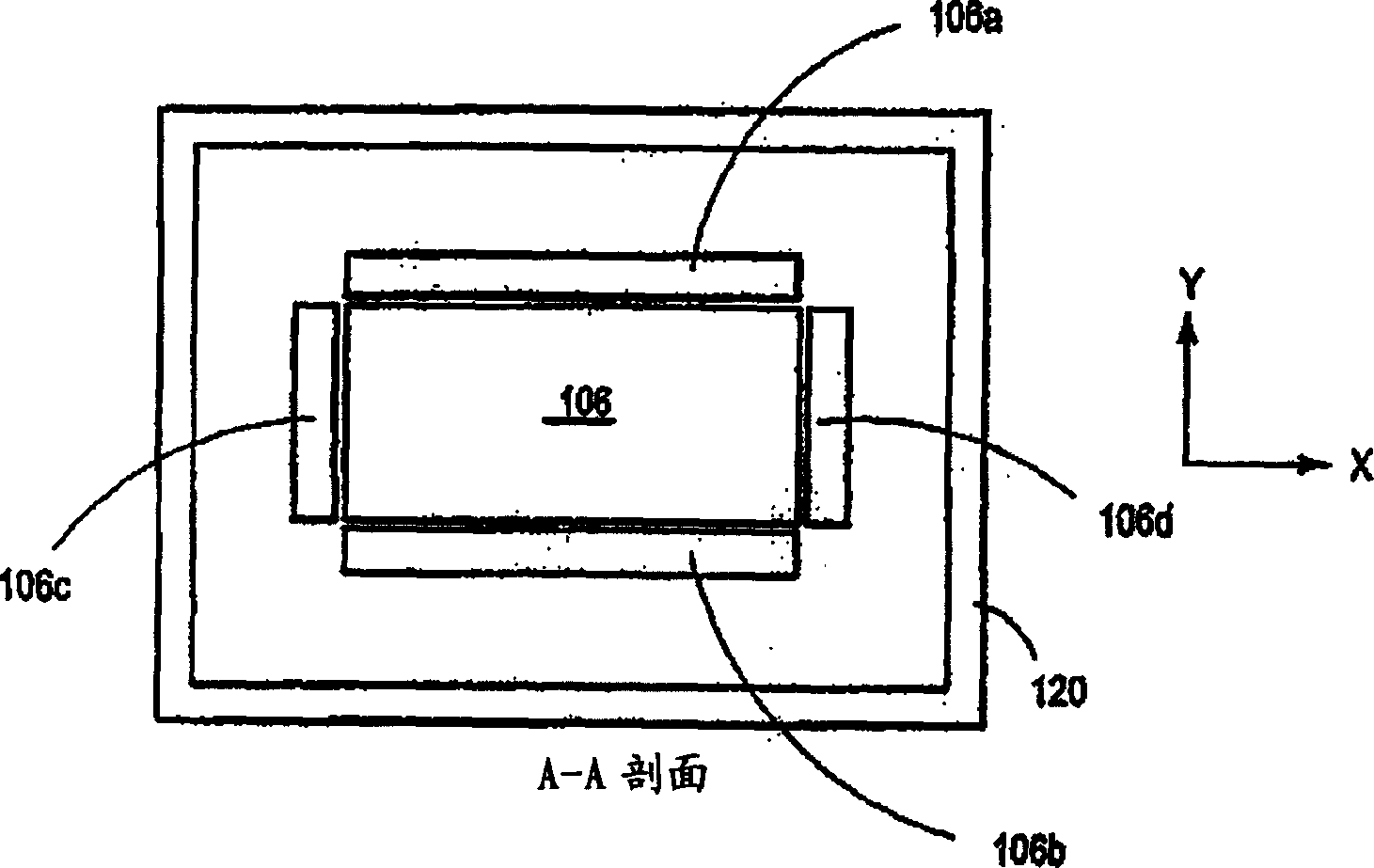
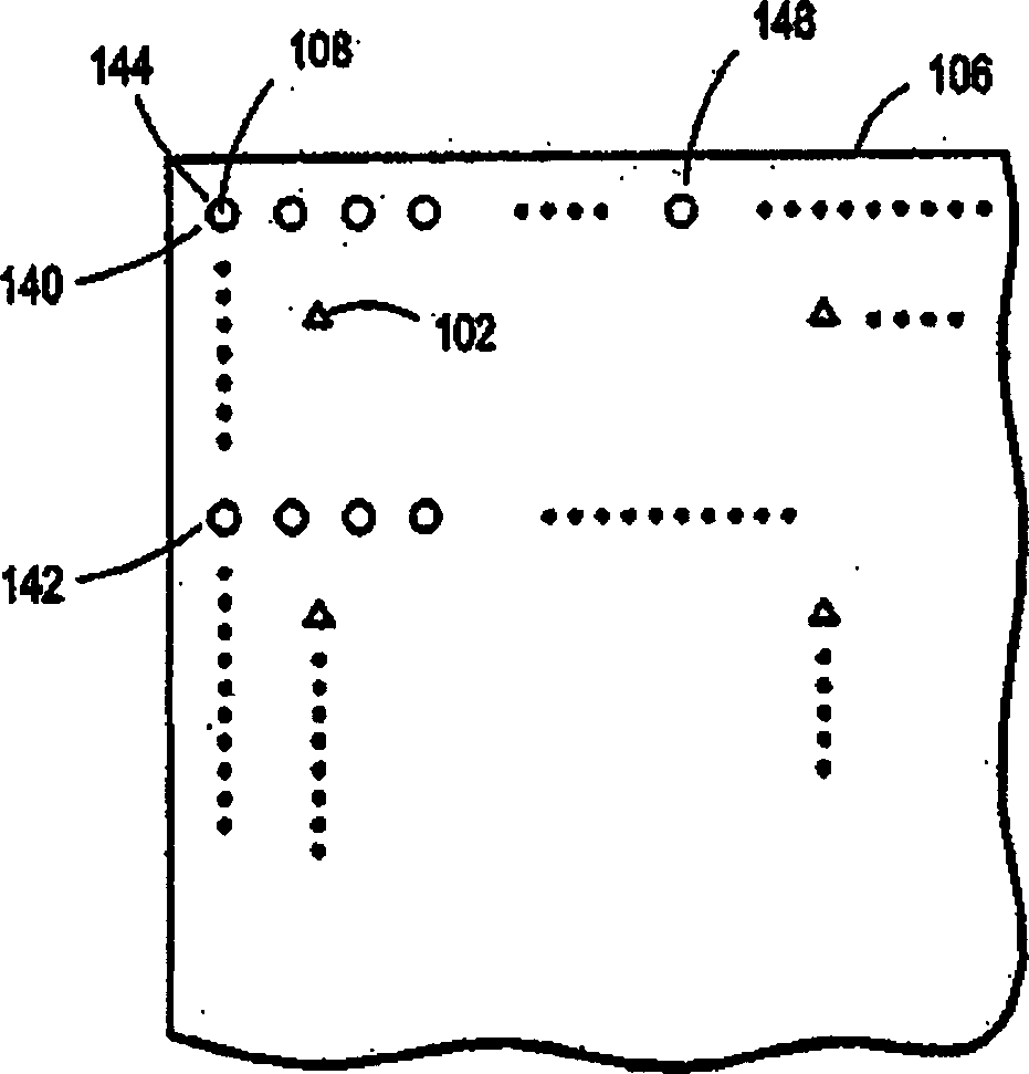
[0018] figure 1 and figure 2 A side view and a top cross-sectional view, respectively, of a storage device 100 are shown, in which a position sensor according to the invention may be employed. The storage device 100 includes: a number of field emitters, such as 102 and 104; a storage medium 106 having a number of storage areas, such as 108; and a microactuator 110 that scans (moves) relative to the field emitters storage medium 106 or vice versa. The storage device 100 may be configured such that each storage area is responsibl...


PUM


Abstract

A position sensor 160, 162, 210, 260 for use in connection with a movable system having a pair of objects 106, 120 that are configured to move relative to one another along an axis through an operative range of motion. The position sensor includes a first plate 178, 180, 222, 226, 266, 268 secured to one of the objects and a pair of second plates 166, 168, 172, 174, 214, 216, 220, 262, 264 secured to the other of the objects. The second plates are adjacent each other and coplanar. The first plate and second plates are configured so that the second plates are spaced from and parallel to the first plate as the objects move relative to one another along the axis. The first plate and second plates are configured so that they form two variable, spaced-plate capacitors 192, 194, 240, 242, 244, 246 having capacitances that vary as the objects move relative to one another within the operative range along the axis. The position sensor is configured to use the capacitances to generate output usable to determine relative position of the objects along the axis.

Description

technical field [0001] The present invention relates to capacitance-based position sensors configured to produce an output capacitance that varies with the relative position of a pair of movable objects. Background technique [0002] The use of capacitance to measure the relative position between two objects is well known. One method of detecting position involves attaching two conductive plates to an object in relative motion. The conductive plates are usually fixed to the object such that they overlap each other and are parallel to each other and are separated by a gap. Together, the two conductive plates and the sandwiched dielectric (such as air) create a capacitance that depends in part on the degree to which the conductive plates overlap each other. As the object moves, the amount of overlap changes, resulting in a corresponding change in capacitance. The relative motion between objects is determined according to the change of capacitance. [0003] One difficulty w...

Claims


Application Information

Patent Timeline
Patent Type & Authority Applications(China)
IPC IPC(8): G01B7/00G01D5/241H01J21/08
CPCG01D5/2412G01R27/00
Inventor D·J·法森S·T·赫恩
Owner HEWLETT PACKARD CO
Why Eureka
Try Eureka