System and methods for sensing acoustic signal using micro-electronical system technology

A signal and sound system technology, applied in the field of micro-electromechanical system technology to sense sound signals, can solve problems such as performance degradation

Inactive Publication Date: 2004-05-19
TEXTRON SYST
View PDF0 Cites 12 Cited by
  • Summary
  • Abstract
  • Description
  • Claims
  • Application Information

AI Technical Summary

Problems solved by technology

wind noise can also mask important acoustic information, degrading the performance of automated systems such as automatic target / object recognition devices, bearing discrimination, etc.

Method used


Image

  • System and methods for sensing acoustic signal using micro-electronical  system technology
  • System and methods for sensing acoustic signal using micro-electronical  system technology
  • System and methods for sensing acoustic signal using micro-electronical  system technology

Examples


Embodiment Construction

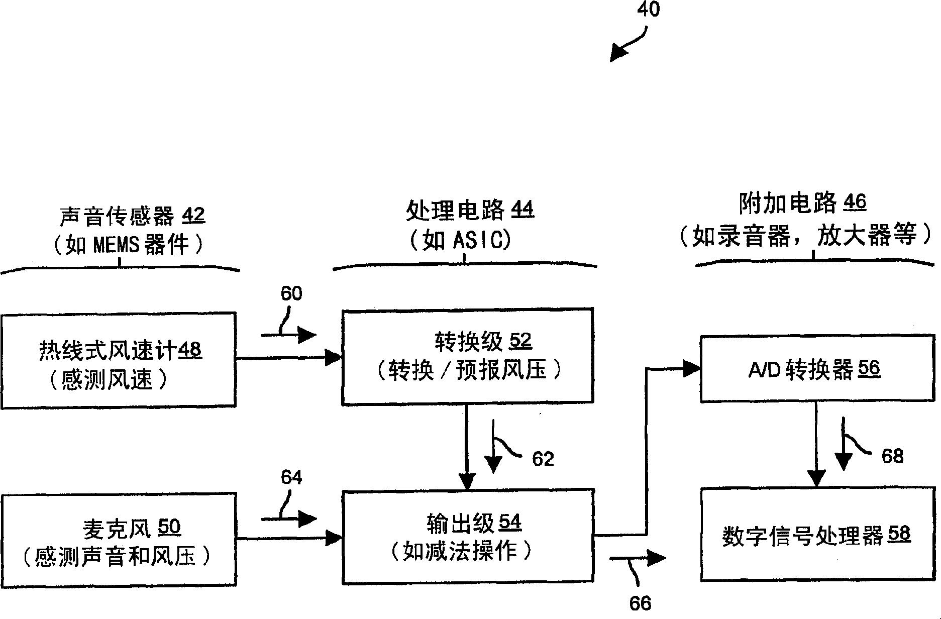
[0064] Embodiments of the present invention relate to methods of obtaining acoustic signals using Micro Electro Mechanical Systems (MEMS) technology. For example, sensing components such as microphones and hot wire anemometers may be disposed within the MEMS device (eg, may be arranged at one location with limited precision separation). Therefore, wind speed, sound and wind pressure can be measured at almost the same location. As a result, a wind pressure signal is generated based on the wind speed at that location, and the generated wind pressure signal is then subtracted from the sound and wind pressure signals at that location, thereby providing an accurate sound signal with wind noise removed.

[0065] figure 1 is a block diagram of an audio transmission system 40 suitable for use with the present invention. The acoustic transmission system 40 includes an acoustic sensor 42 and a processing circuit 44 . The audio transmission system 40 also includes additional circuitry...


PUM


Abstract

An acoustic system has an acoustic sensor and a processing circuit. The acoustic sensor includes a base, a microphone having a microphone diaphragm supported by the base, and a hot-wire anemometer having a set of hot-wire extending members supported by the base. The set of hot-wire extending members defines a plane which is substantially parallel to the microphone diaphragm. The processing circuit receives a sound and wind pressure signal from the microphone and a wind velocity signal from the hot-wire anemometer, and provides an output signal based on the sound and wind pressure signal from the microphone and the wind velocity signal from the hot-wire anemometer (e.g., accurate sound with wind noise removed). The configuration of the hot-wire extending members defining a plane which is substantially parallel to the microphone diaphragm can be easily implemented in a MEMS device making the configuration suitable for miniaturized applications.

Description

technical field [0001] The present invention relates to systems and methods for sensing acoustic signals using MEMS technology. Background technique [0002] Microphones are converters that convert air pressure samples (ie, acoustic signals) into electrical signals. In a typical dynamic microphone, the microphone's diaphragm moves the coil against a magnetic field, causing current to flow into the coil. In a typical condenser microphone, the microphone's diaphragm (such as a charged metal electrode plate, electret, etc.) moves relative to a rigid backplate, allowing current to flow from the power source, creating a gap between the microphone diaphragm and the rigid backplate. constant potential difference. [0003] Wind noise interferes with the microphone's ability to sense sound signals. For example, when a person speaks into a microphone, wind noise can obscure the person's voice, making the sound from devices connected to the microphone (such as amplifiers, recorders,...

Claims


Application Information

Patent Timeline
Patent Type & Authority Applications(China)
IPC IPC(8): G01P5/12G01S7/521H04R3/00H04R23/00H04R23/02
CPCH04R23/00
Inventor 霍华德·C·雀埃姆尔·S·比拉
Owner TEXTRON SYST
Why Eureka
Try Eureka