Power supply driver circuit

a driver circuit and power supply technology, applied in the direction of electric variable regulation, process and machine control, instruments, etc., can solve the problem of difficulty in detecting an accurate current value, and achieve the effect of improving the response of current sensing and raising the current sensing accuracy

Inactive Publication Date: 2006-11-21
RENESAS ELECTRONICS CORP
View PDF2 Cites 188 Cited by
  • Summary
  • Abstract
  • Description
  • Claims
  • Application Information

AI Technical Summary

Benefits of technology

[0012]It is an object of the present invention to provide technology making it possible to sense a current with high accuracy, even rapidly after switching, without being subject to the influence of the switching of the power transistors, and based on that, enabling current control with high accuracy and high speed.
[0019]According to the aforementioned technology, since the node voltage is set to the potential for the current sensing operating state and because it becomes possible to selectively set the potential in the node where the voltage becomes undefined or the node in which a surge voltage is generated, a shift in the node potential does not occur as has conventionally been the case, so it becomes possible to improve the accuracy and response of the sensed currents to the output current of the switched-mode power supply equipment, the power supply driver circuit, and the module.
[0021](1) By suppressing the influence of an undefined voltage state due to the switching of a power supply driver, it becomes possible to improve the response of the current sensing with respect to the output current as well as to raise the current sensing accuracy independently of the timing of the current sensing.

Problems solved by technology

However, with current sensing technology based on power supply systems such as mentioned above, the following problem areas were found to exist by the inventors.
As a result, when the power transistors of the switched-mode power supply switch, there ends up occurring a response delay, so there is the problem that it becomes difficult to sense an accurate value for the current.

Method used


Image

  • Power supply driver circuit
  • Power supply driver circuit
  • Power supply driver circuit

Examples


embodiment 1

1. Embodiment 1

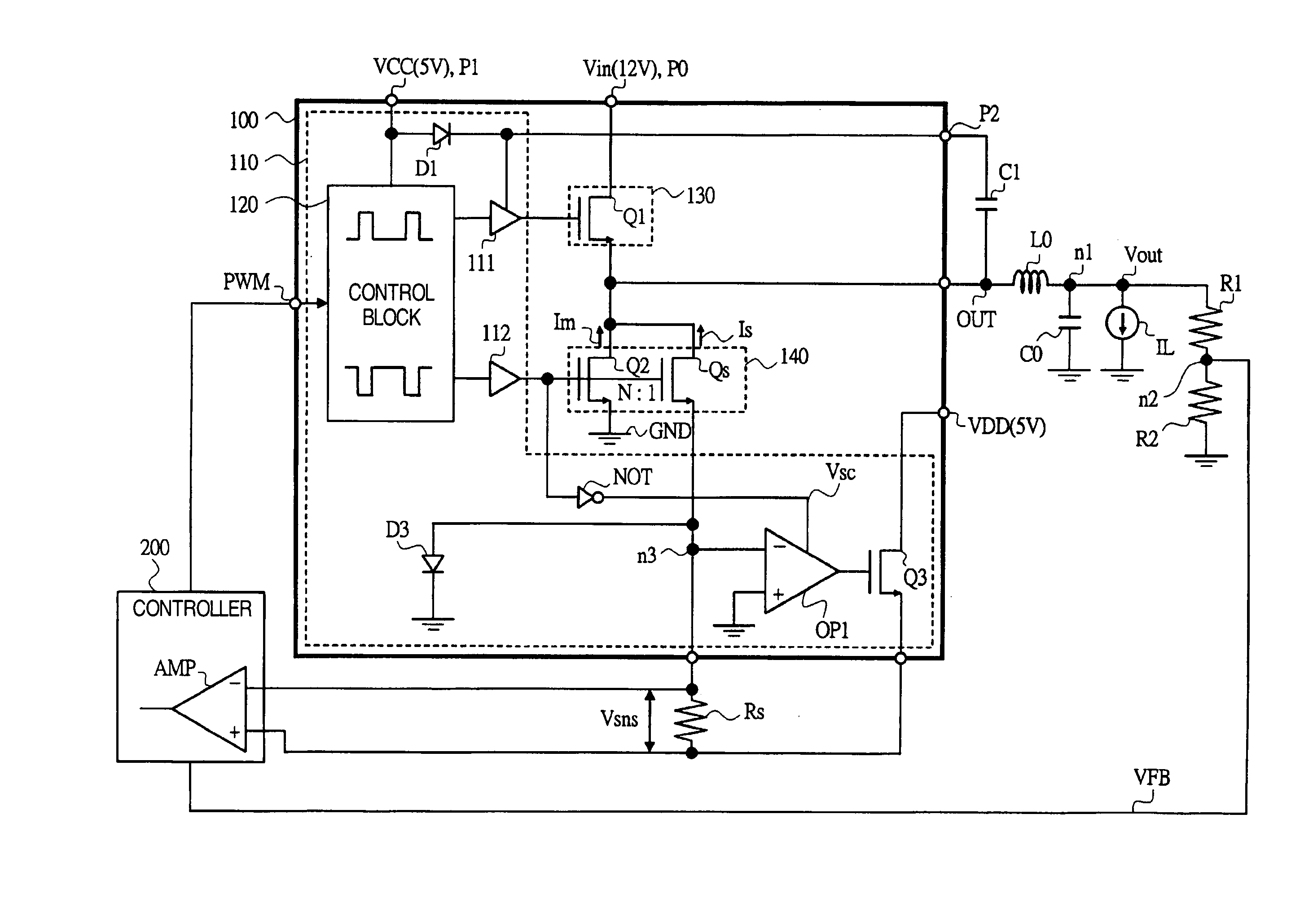
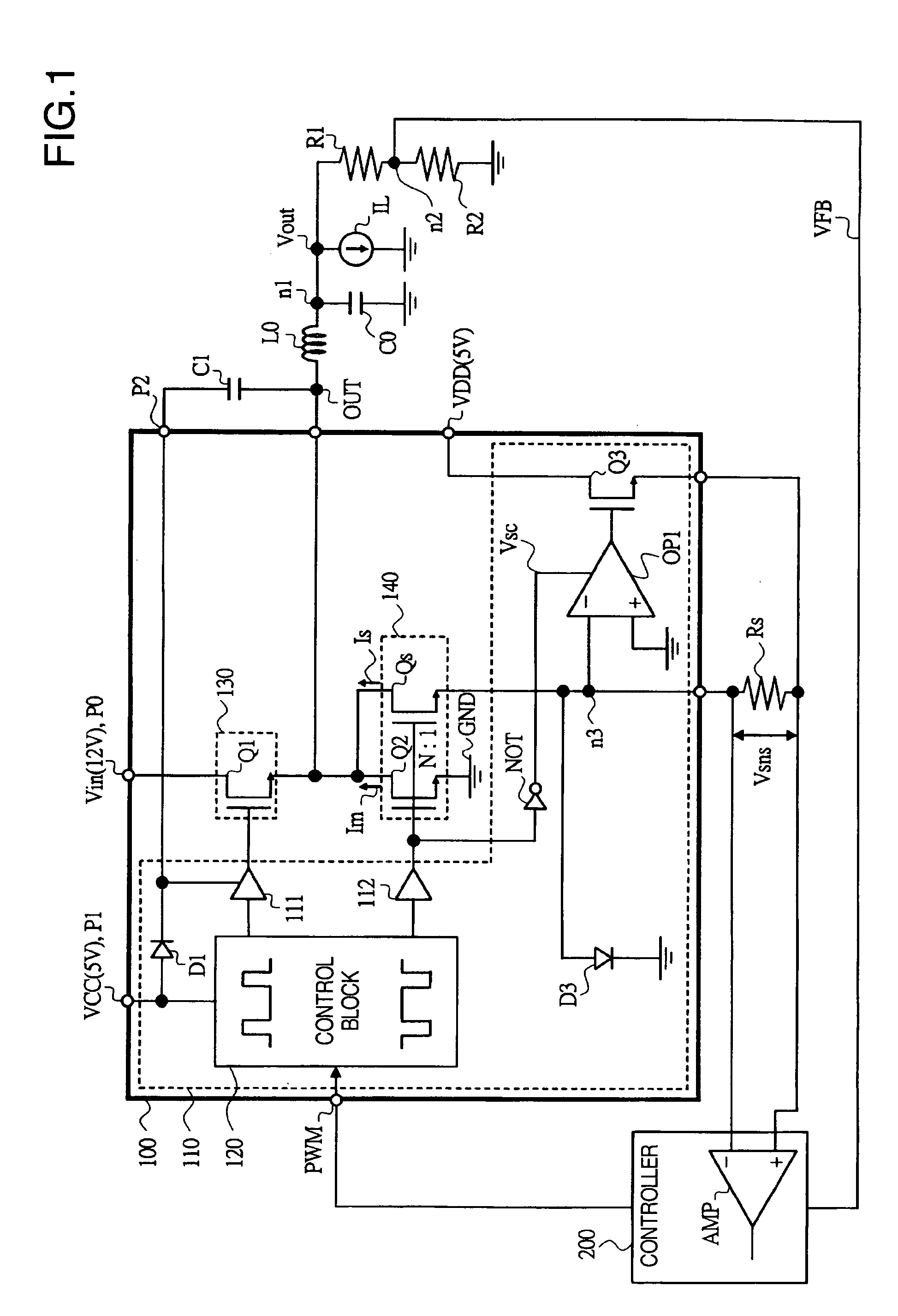
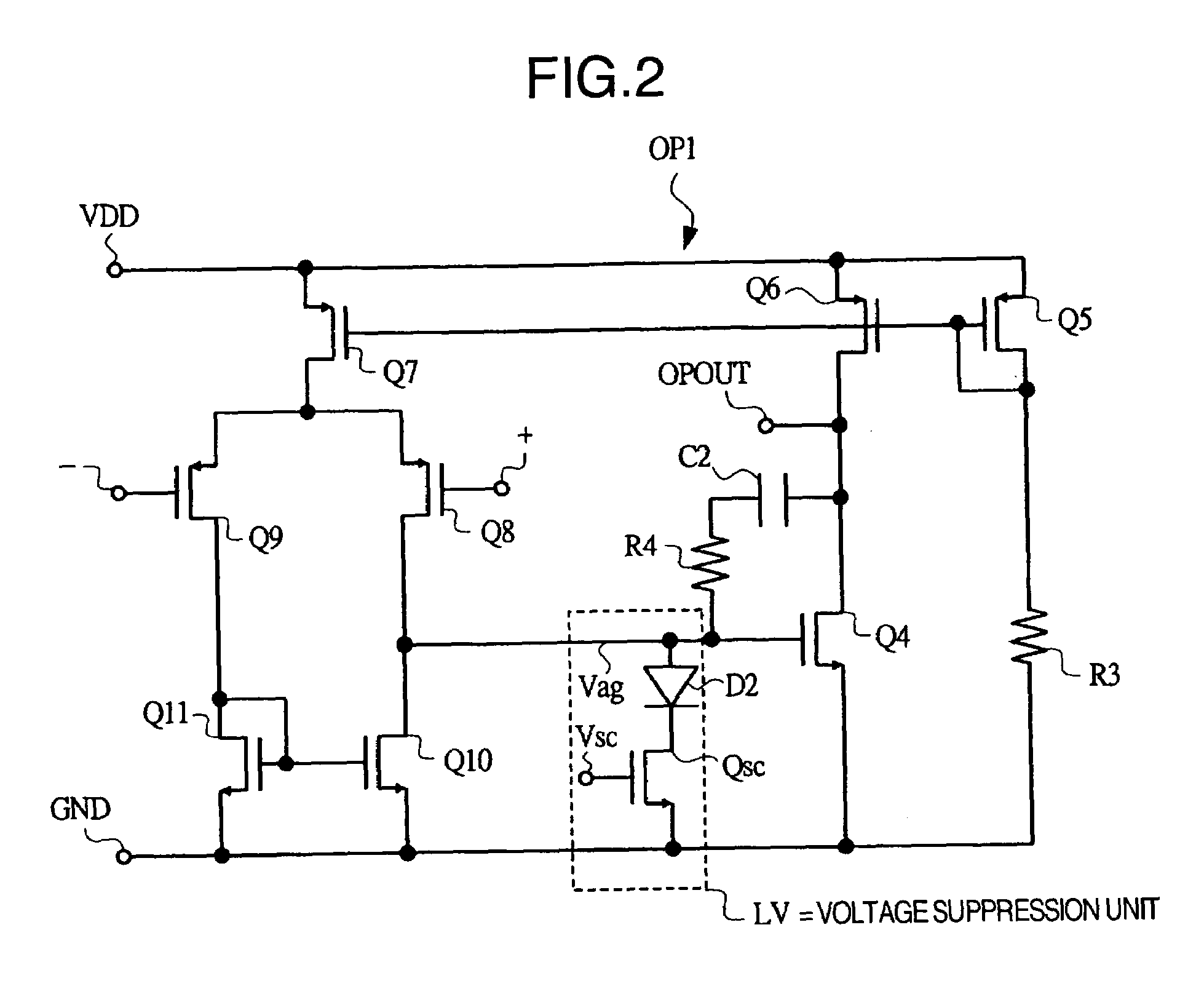
[0037]FIG. 1 is a circuit diagram of an example of a switching regulator based on Embodiment 1 of the present invention, FIG. 2 is a circuit diagram of an example of an operational amplifier provided in the switching regulator of FIG. 1, and FIG. 3 is a timing chart showing the timing of the signals, for each of its parts, of the switching regulator of FIG. 1.

[0038]In Embodiment 1, the switching regulator (the power supply driver circuit) comprised of a buck-type regulator and is composed, as shown in FIG. 1, of a power supply driver module 100, a controller 200, a coil L0, a smoothing capacitor C0, resistors R1, R2, a sensing resistor (a current sensing resistor) Rs, and so forth.

[0039]Coil L0 is an inductor connected between output terminal OUT of module 100 and a load. Smoothing capacitor C0 is connected between a node n1 and a ground point on the load side of coil L0 and stabilizes an output voltage Vout.

[0040]Resistors R1, R2 are connected in series between smoot...

embodiment 2

2. Embodiment 2

[0071]FIG. 4 is a circuit diagram showing an example of a switching regulator according to Embodiment 2 of the present invention and FIG. 5 is a timing chart showing the timing of the signals, for each of its parts, of the switching regulator of FIG. 4.

[0072]In Embodiment 2, FIG. 4 is a circuit diagram showing another example of a power supply driver module, equipped with a power supply driver circuit relating to the present invention, and a buck-type switching regulator applying same, and FIG. 5 shows its timing chart.

[0073]Embodiment 2 has a configuration wherein a level shifter circuit LS is provided between the gate of transistor Q1 and operational amplifier OP1 and is input to the gate of switching transistor Qsc, in the circuit in FIG. 1 of the Embodiment 1, in which an inverter circuit NOT is provided between the gate of transistor Q2 and operational amplifier OP1, and the output of which is input as gate voltage Vsc to the switch of diode D2.

[0074]The gate vol...

embodiment 3

3. Embodiment 3

[0077]FIG. 6 is a circuit diagram showing an example of a switching regulator according to Embodiment 3 of the present invention, and FIG. 7 is a timing chart showing the timing of the signals, for each of its parts, of the switching regulator of FIG. 6.

[0078]In Embodiment 3, the buck-type regulator has a configuration wherein is disposed, in series with the inverter circuit NOT disposed between the gate of transistor Q2 and operational amplifier OP1 in FIG. 1 of the aforementioned Embodiment 1, a delay circuit DL (a timing setting means). Further, the order of inverter circuit NOT and delay circuit DL is of course irrelevant in this case.

[0079]According to this configuration, as shown in FIG. 7, it is possible to set the gate voltage Vsc of switch transistor Qsc with arbitrary timing. As a result, even if the timing of the voltage generated at gate voltage Vag is not synchronized with the gate voltage of transistor Q1, etc., it becomes possible for it to be subjected...


PUM


Abstract

A power supply driver circuit with low power losses and desired response characteristics with respect to changes in output and its miniaturization is provided. In a driver IC constituting a switched-mode power supply equipment controlling the switching, by pulse width modulation, of first and second power transistors passing a current in a coil, and outputting a voltage bucked or boosted from an input voltage, current sensing with desired responsiveness is enabled by providing a switching transistor between an inverted input terminal and a non-inverted input terminal of an operational amplifier, preventing, while the second power transistor is ON, the generation of a potential which is undefined when first power transistor is ON, i.e. when the second power transistor is OFF, and maintaining a node potential in a state in which the potential is well defined.

Description

BACKGROUND OF THE INVENTION[0001]1. Field of the Invention[0002]The present invention pertains to current sensing of a piece of power supply equipment generating direct-current voltage, and in particular, to technology valid for improving the current sensing accuracy in a power supply driver circuit driving a power transistor by means of switching control.[0003]The power supply driver circuit of the present invention is suited to a power supply driver circuit driving the power transistors of a piece of switched-mode power supply equipment controlling switching, e.g. with the PWM (Pulse Width Modulation) method, converting an input voltage, and obtaining an output voltage, and to a driver module equipped with the circuit, as well as to a switched-mode power supply utilizing the module.[0004]2. Description of the Related Art[0005]When it comes to electronic equipment in recent years, articles equipped with a microprocessor (below called CPU, Central Processing Unit) as a system contro...

Claims


Application Information

Patent Timeline
Patent Type & Authority Patents(United States)
IPC IPC(8): G05F1/613
CPCH02M3/1588H02M2001/0009Y02B70/1466Y02B70/10H02M1/0009
Inventor ISHIGAKI, TAKUYASASE, TAKASHIKANOUDA, AKIHIKOTATENO, KOJIKUDO, RYOTARO
Owner RENESAS ELECTRONICS CORP
Why Eureka
Try Eureka