Locking means

A locking device and keyhole technology, applied in the application of building locks, vehicle locks, locks, etc., to prevent wrong assembly

Inactive Publication Date: 2004-05-26
PIOLAX CO LTD
View PDF3 Cites 25 Cited by
  • Summary
  • Abstract
  • Description
  • Claims
  • Application Information

AI Technical Summary

Problems solved by technology

[0011] In addition, this fear may occur when the slide pin protrudes into the lock hole when the glove box main body in the open state is closed.

Method used


Image

  • Locking means
  • Locking means
  • Locking means

Examples


no. 1 example

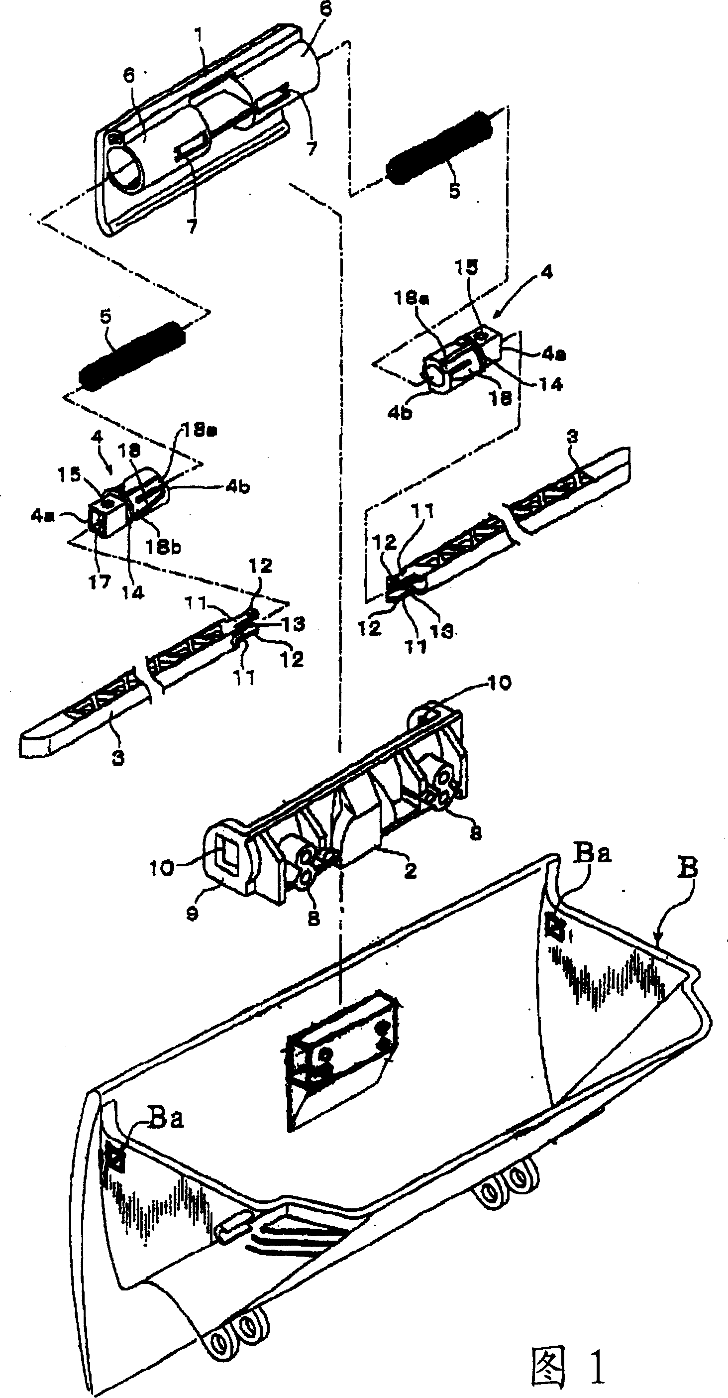
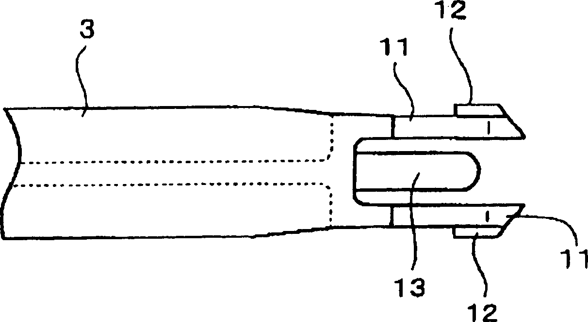
[0048] Also, as shown in FIG. 1, the locking device according to the first embodiment includes: an operating handle 1; a support frame 2; a pair of left and right sliding pins 3; a pair of left and right cam parts 4; spring 5. The operating handle 1 is supported to be swingable within a concave portion defined in the front wall of the glove box main body. The support frame 2 fixes the operating handle 1 to the connecting wall extending to the inner side of the concave part through screw connection. The cam members 4 push the slide pins 3 to extend and retract them, respectively. Compression coil springs 5 ​​respectively push said slide pins 3 toward the lock holes defined in the instrument panel.

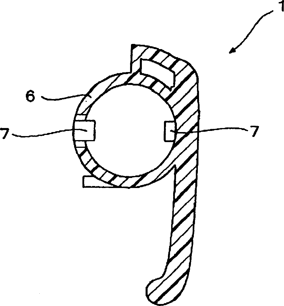
[0049] as well figure 2 As shown, on the back side of the operating handle, a pair of left and right cylindrical portions 6 each for accommodating the slide pin 3 and the compression coil spring 5 are integrally formed. On inner surfaces disposed opposite to each other in each c...

no. 2 example

[0061] As shown in Figure 11, the locking device according to the second embodiment includes: an operating handle 101, a support frame 102, a pair of left and right sliding pins 103, a pair of left and right cam parts 104, two compression coil springs 105 and O Ring 124. The operating handle 101 is disposed inside the concave portion defined in the front wall of the glove box body to open and close the glove box main body. The supporting frame 102 is threadedly coupled to the connecting wall extending to the inner side of the concave portion and supports the operating handle 101 so that it can swing. The cam members 104 push the corresponding slide pins 103 to extend and retract, respectively. The compression coil springs 105 respectively push the slide pins 103 toward the direction of the lock holes defined in the instrument panel. An O-ring 124 is connected to the cam member to provide braking force as will be described below.

[0062] Such as Figure 12 As shown, on the...

no. 3 example

[0085] Next, a locking device according to a third embodiment will be described. The locking device according to the third embodiment differs from that of the second embodiment in that it acts as a central locking device for a glove box. The basic structure of the locking device according to the third embodiment is similar to that of the second embodiment. That is, if Figure 18 As shown, the locking device includes an operating handle 101 , a support frame 102 , a sliding pin 103 , a cam member 104 , a compression coil spring 105 and an O-ring 124 .

[0086] However, since the third embodiment described has an operating handle 101 with a vertical swing axis as a central locking device, a separate cylindrical portion 106 is formed on the rear side of the handle. A single cam member 104 having an accommodation groove 125 fitted with an O-ring 124 and a single compression coil spring 105 are inserted into the single cylindrical portion 106 in up and down directions. A curved ...


PUM


Abstract

A lock apparatus includes a operation handle, a pair of springs movably supported by the container member, a pair of slide pins urged in directions of lock holes defined on the support member by the springs, respectively, and a pair of cam members to which rear end portions of the slide pins are fitted, respectively, to urge each slide pin to project and retract. When the operation handle is operated in a swing manner, a front end portion of each slide pin is retracted from each lock hole of the support member against pressure of each spring. Engagement holes are defined on opposed surfaces of each front end portion of the cam member having a cylindrical shape. Each rear end portion of the slide pin is formed in a bifurcated structure to have elastic pieces. Each of elastic pieces has a protrusion for detachably engaging with each of engagement holes.

Description

[0001] This disclosure is related to the subject matter of Japanese Patent Application No. 2002-323616 filed Nov. 7, 2002 and Japanese Patent Application No. 2003-364097 filed Oct. 24, 2003, the entire contents of which are hereby incorporated by reference. technical field [0002] The invention relates to a locking device for use in, for example, an axially supported rotatable glove box located on the dashboard of a vehicle. Background technique [0003] JP-A-Hei.4-60079, although not specifically shown, discloses a locking device in which a pair of left and right link rods are axially rotatably supported in a housing provided by a glove box so that a A pair of slide pins are fixed to an upper end portion of each of the left and right links, wherein the slide pins are freely accessible in lock holes defined in the instrument panel. A tension coil spring is installed between the lower end portions of the left and right links, and the spring generally pushes the corresponding...

Claims


Application Information

Patent Timeline
Patent Type & Authority Applications(China)
IPC IPC(8): B60R7/06E05B65/12E05C1/14E05C9/04
CPCY10T292/0964E05C1/145Y10T292/0961E05B83/30Y10T292/084Y10T292/0978Y10T292/0971B60R7/06E05C9/045Y10T292/0837
Inventor 加藤幸一新仓昇大河原俊彦
Owner PIOLAX CO LTD
Why Eureka
Try Eureka