Bus bar module

a bus bar module and bus bar technology, applied in secondary cell servicing/maintenance, battery components, cell components, etc., can solve the problems of difficult to improve workability (assembly), difficult to stretch and shrink the bus bar module, etc., to facilitate the punching process and facilitate the flexible board. , the effect of improving the conformability to the deformation of the battery assembly

Active Publication Date: 2020-01-16
YAZAKI CORP
View PDF0 Cites 1 Cited by
  • Summary
  • Abstract
  • Description
  • Claims
  • Application Information

AI Technical Summary

Benefits of technology

[0027]According to the bus bar module of the structure of the above [4], the branch line of the circuit body is formed of the first branch portion extending in the direction intersecting with the length direction of the main line and the second branch portion connecting with the first branch portion and having the folded portion. This facilitates the process of punching the flexible board and the like when the circuit body is actually manufactured.
[0028]According to the bus bar module of the structure of the above [5], it is made easy for the main line to maintain the condition of extending in the assembled direction (for example, along the upper surface of the battery assembly) while absorbing the stretch and shrinkage and the manufacturing variations of the battery assembly by the branch line. Consequently, the main line of the circuit body can more appropriately maintain the condition of being away from the upper surfaces of the single cells as described above.
[0029]According to the present invention, a bus bar module can be provided that is excellent in the assemblability to the battery assembly and the conformability to the deformation of the battery assembly.

Problems solved by technology

As a consequence, if the voltage detection line is formed by bundling the multiplicity of electric wires, the overall stiffness of the voltage detection line (accordingly, the stiffness of the bus bar module) increases, so that it can be difficult to improve the workability (assemblability) at the time of assembly of the bus bar module to the battery assembly.
For the same reason, it can be difficult for the bus bar module to stretch and shrink so as to be sufficiently conform to the deformation and the manufacturing variations of the battery assembly.

Method used


Image

  • Bus bar module
  • Bus bar module
  • Bus bar module

Examples


embodiment

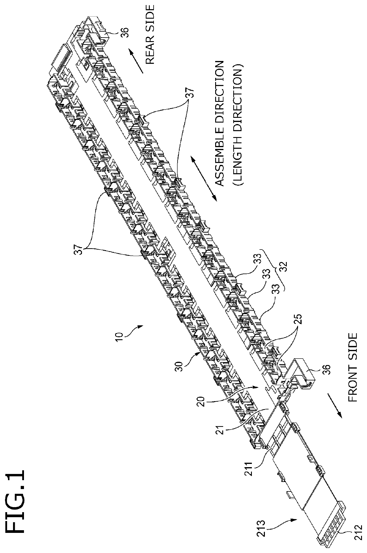
[0055]Hereinafter, referring to the drawings, a bus bar module 10 according to an embodiment of the present invention will be described. The bus bar module 10 according to the present embodiment is used in such a manner as to be assembled to a battery assembly (a battery module where a plurality of single cells are disposed so as to be assembled) as a driving power source mounted on, for example, an electric car and a hybrid car.

(Structure of the Battery Assembly)

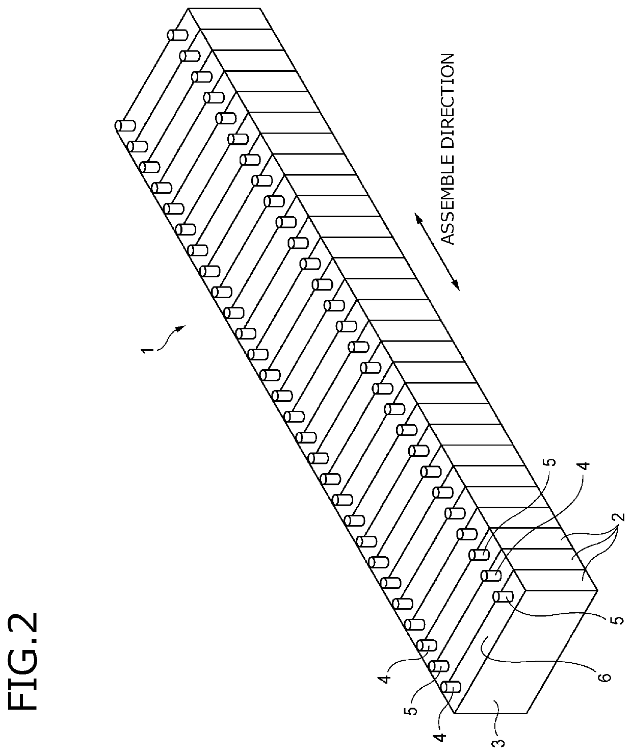
[0056]First, a battery assembly 1 to which the bus bar module 10 of the present embodiment is attached will be described. As shown in FIG. 2, the battery assembly 1 is formed by linearly connecting a plurality of single cells 2. The single cells 2 each have a positive electrode 4 and a negative electrode 5 provided so as to project on the top portion of a battery body (body) 3 formed in a rectangular shape. The positive electrode 4 and the negative electrode 5 are disposed away from each other on an electrode surface 6 of t...


PUM

PropertyMeasurementUnit
flexibleaaaaaaaaaa
stretchableaaaaaaaaaa
thicknessaaaaaaaaaa

Abstract

A bus bar module is attached to a battery assembly having a plurality of single cells which are assembled to each other along a first direction. The bus bar module includes a circuit body, a bus bar, and a holder. The circuit body includes a main line that extends in the first direction, a branch line that extends from the main line so as to branch from the main line, and a connection portion provided in a position close to a distal end of the branch line rather than a folded portion of the branch line and configured to be connected to the bus bar.

Description

CROSS REFERENCE TO RELATED APPLICATIONS[0001]This application is based on Japanese Patent Application (No. 2018-130912) filed on Jul. 10, 2018 and Japanese Patent Application (No. 2018-144237) filed on Jul. 31, 2018 and, the contents of which are incorporated herein by reference.BACKGROUND OF THE INVENTION1. Field of the Invention[0002]The present invention relates to a bus bar module.2. Description of the Related Art[0003]Conventionally, a bus bar module has been used in such a manner as to be assembled to a battery assembly (a battery module where a plurality of battery cells are disposed so as to be assembled) as a driving power source mounted on, for example, an electric car and a hybrid car (for example, see JP-A-2014-220128).[0004]A bus bar module described in JP-A-2014-220128 is provided with: a plurality of bus bars connecting between the positive electrodes and the negative electrodes of the battery cells assembled so as to adjoin each other; and a voltage detection line co...

Claims


Application Information

Patent Timeline
Patent Type & Authority Applications(United States)
IPC IPC(8): H01M2/20H01M10/42H01M10/48H01M2/10H05K1/02H05K1/11H01M50/209H01M50/507
CPCH01M2/206H05K1/028H01M10/425H01M2/1077H01M10/482H05K1/118H01M50/531H01M2220/20H01M50/507H01M50/209Y02E60/10
Inventor TAKAMATSU, MASAHIROICHIKAWA, YOSHIAKIMAKINO, KIMITOSHIKOBAYASHIYASUDA, TOMOJI
Owner YAZAKI CORP
Why Eureka
Try Eureka