Self-moving die punching machine

A stamping machine and self-moving technology, which is applied in the field of stamping machines, can solve the problems of low drilling efficiency, time-consuming and labor-consuming, and achieve the effect of improving the drilling efficiency

Inactive Publication Date: 2020-09-22
刘建
View PDF6 Cites 10 Cited by
  • Summary
  • Abstract
  • Description
  • Claims
  • Application Information

AI Technical Summary

Problems solved by technology

[0004] In order to overcome the disadvantages of time-consuming and labor-intensive manual punching and low punching efficiency, the technical problem is: to provide a method that can automatically punch holes in composite slatted plates, and can punch out multiple holes at one time to improve the punching efficiency. Self-moving die stamping machine

Method used


Image

  • Self-moving die punching machine
  • Self-moving die punching machine
  • Self-moving die punching machine

Examples


Embodiment 1

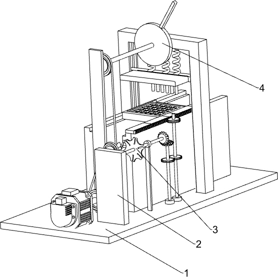
[0030] A self-moving die stamping machine, such as figure 1 As shown, it includes a base 1, a bracket 2, a moving mechanism 3 and a punching mechanism 4, a bracket 2 is installed on the front side of the right part of the base 1, a moving mechanism 3 is arranged on the base 1, and a punching mechanism 4 is arranged on the base 1. The punching mechanism 4 is connected with the movement mechanism 3 .

[0031] When the composite slatted board needs to be stamped and punched, the composite slatted board is manually placed in the parts of the movement mechanism 3, so that the position of the last row of composite slatted boards to be punched is directly below the parts of the punching mechanism 4 , and then start the parts of the moving mechanism 3, and the parts of the moving mechanism 3 will drive the composite slatted plate to move back intermittently. At the same time, the parts in the punching mechanism 4 will reciprocate up and down. When the composite slatted plate stops mov...

Embodiment 2

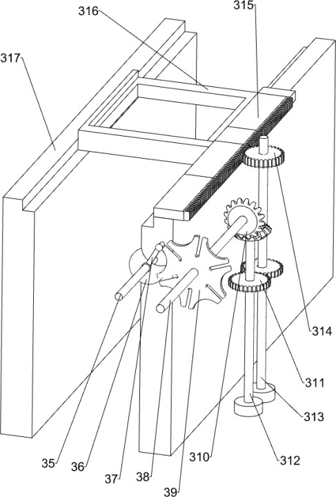
[0033] In particular, as Figure 2-3 As shown, the motion mechanism 3 includes a motor 31, a first pulley 32, a first flat belt 33, a first rotating shaft 34, a second rotating shaft 35, a half-moon disc 36, a first driving lever 37, a third rotating shaft 38, a hexagonal Disc 39, steering gear 310, first gear 311, fourth rotating shaft 312, fifth rotating shaft 313, second gear 314, rack 315, bearing frame 316 and first slide rail 317, base 1 middle part front side is installed with Motor 31, the output shaft of motor 31 is connected with the first rotating shaft 34, and the left rear side of support 2 top is rotated and is provided with the second rotating shaft 35, and the front side of the second rotating shaft 35 and the middle part of the first rotating shaft 34 are all provided with the first belt pulley 32 A first flat belt 33 is wound between the two first pulleys 32, a half-moon disc 36 is installed on the rear side of the second rotating shaft 35, and a first lever ...

Embodiment 3

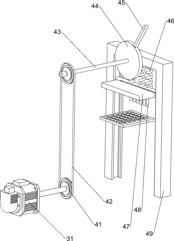
[0036] according to figure 2 and Figure 4As shown in the diagram, the punching mechanism 4 includes a second pulley 41, a second flat belt 42, a sixth rotating shaft 43, a pressing turntable 44, a second driving lever 45, a spring 46, a push plate 47, a punching rod 48 and The second slide rail 49, the front side of the middle part of the base 1 is rotatably provided with a sixth rotating shaft 43, the sixth rotating shaft 43 front side and the first rotating shaft 34 rear side are equipped with a second pulley 41, and the two second pulleys 41 pass through the second The flat belt 42 is connected, the sixth rotating shaft 43 rear end is equipped with a pressing turntable 44, the pressing rotating disc 44 top is provided with a second shift lever 45, the rear side of the base 1 is provided with a second slide rail 49, the sixth rotating shaft 43 rear end and The front side of the upper part of the second slide rail 49 is rotationally connected, and a push plate 47 is slidin...


PUM


Abstract

The invention relates to a punching machine, in particular to a self-moving die punching machine. The self-moving die punching machine can automatically punch a composite leaking plate, punch a plurality of holes at one time, and improve the punching efficiency. According to the technical scheme, the self-moving die punching machine comprises a base and a punching mechanism, wherein a support is installed on the front side of the base; a movement mechanism is arranged on the base; and the punching mechanism is installed on the base and connected with the movement mechanism. According to the self-moving die punching machine, the composite leaking plate can be driven to move intermittently through the movement mechanism, so that the different parts of the composite leaking plate are punchedconveniently; the composite leaking plate can be punched automatically through the punching mechanism; meanwhile, through the design of a plurality of punching rods, the plurality of holes can be punched simultaneously, so that the punching efficiency is improved; and waste falling in the punching process is collected through a waste collecting box instead of being swept manually.

Description

technical field [0001] The invention relates to a stamping machine, in particular to a self-moving mold stamping machine. Background technique [0002] At present, in the animal husbandry industry, in order to facilitate the treatment of animal manure and maintain the sanitation of the farm, most manufacturers will use composite slatted panels in the breeding factory. However, composite slatted panels usually have no gaps when they are first produced. , it is necessary to manually use tools to punch holes in the composite slatted board, so that the gaps are evenly distributed on the composite slatted board. However, with this punching method, workers can only punch out one gap at a time. The punching work of the board needs to be manually operated repeatedly, and the same composite slatted board is punched multiple times. The whole punching process needs to consume a lot of time and energy, and the efficiency of punching is low. [0003] In view of the shortcomings of the a...

Claims


Application Information

Patent Timeline
Patent Type & Authority Applications(China)
IPC IPC(8): B21D28/34B21D28/26B21D43/20B21D43/13
CPCB21D28/26B21D28/34B21D43/13B21D43/20
Inventor 刘建
Owner 刘建
Why Eureka
Try Eureka