
Concrete floor secondary beam combined prefabricated member and production method

A technology for prefabricated components and prefabricated concrete slabs, applied to floors, building components, manufacturing tools, etc., can solve the problems of cumbersome cast-in-place formwork supporting procedures, limited concrete curing conditions, and high cross-section of secondary beams, so as to facilitate the laying of pipelines, improve The effect of improved curing conditions, construction speed and quality

Pending Publication Date: 2020-07-17
BEIJING UNIV OF TECH
View PDF7 Cites 2 Cited by
  • Summary
  • Abstract
  • Description
  • Claims
  • Application Information

AI Technical Summary

Problems solved by technology

However, in the traditional cast-in-place concrete slab, the concrete and steel bars of the slab will bear part of the negative bending moment, and the slab does have a certain combined effect with the main beam of the prefabricated component. Therefore, when an earthquake occurs, the damage that generally occurs is that of strong beams and weak columns. destroy
[0003] For traditional cast-in-place slabs, floor slabs and secondary beams can be combined without stress, but as cast-in-place structures, floor slabs and secondary beams are combined under stress, and the combination effect is weak. Considering that the combination is unsafe, the secondary beam section is high and the deflection is large
Moreover, the cast-in-place formwork process is cumbersome, and the concrete curing conditions are limited, which is prone to environmental pollution

Method used


Image

  • Concrete floor secondary beam combined prefabricated member and production method
  • Concrete floor secondary beam combined prefabricated member and production method
  • Concrete floor secondary beam combined prefabricated member and production method

Examples


Embodiment Construction

[0033] In order to make the purpose, technical solutions and advantages of the embodiments of the present invention clearer, the technical solutions in the embodiments of the present invention will be clearly and completely described below in conjunction with the drawings in the embodiments of the present invention. Obviously, the described embodiments It is a part of embodiments of the present invention, but not all embodiments. Based on the embodiments of the present invention, all other embodiments obtained by persons of ordinary skill in the art without making creative efforts belong to the protection scope of the present invention.

[0034] Below in conjunction with accompanying drawing, the present invention is described in further detail:

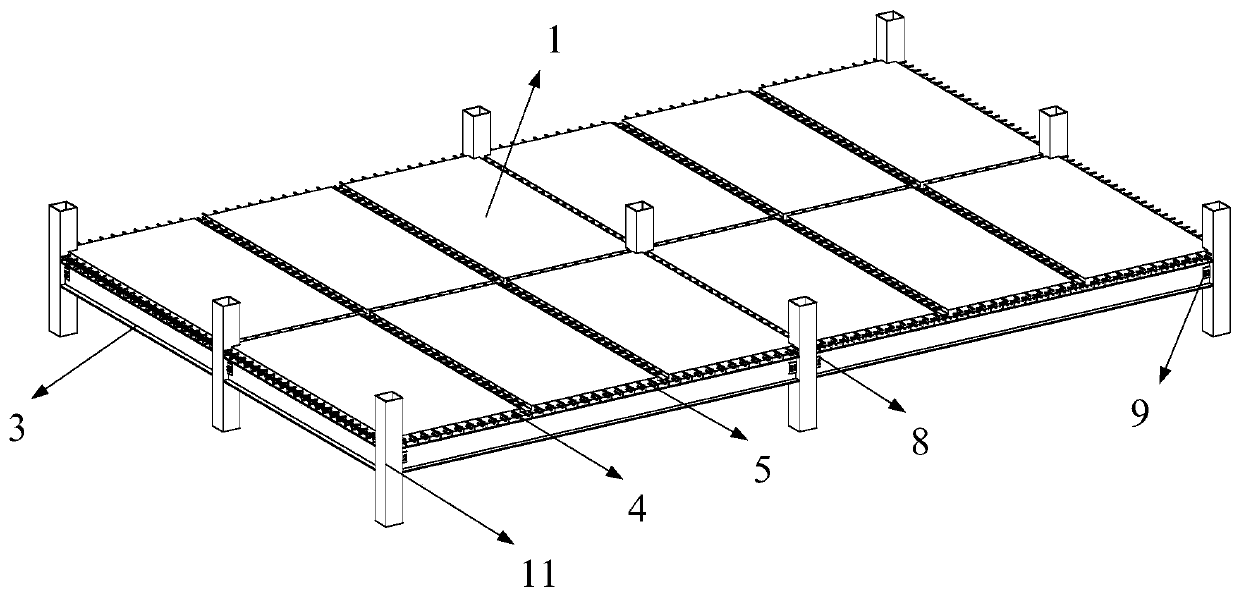
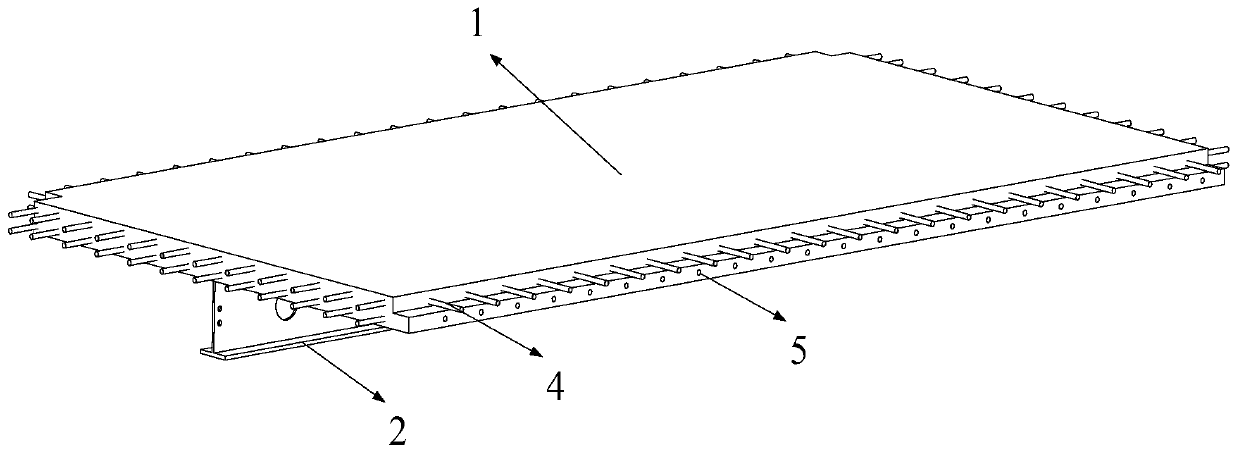
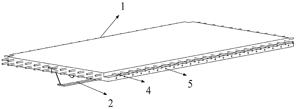
[0035] Such as figure 1 As shown, a composite prefabricated component of a concrete floor secondary beam provided according to the present invention includes: a prefabricated concrete slab 1 and an H-shaped steel secondary beam 2, t...


PUM


Abstract

The invention discloses a concrete floor secondary beam combined prefabricated member and a production method. The concrete floor secondary beam combined prefabricated member comprises a prefabricatedconcrete plate and an H-shaped steel secondary beam, and the prefabricated concrete plate is poured by concrete; and studs are welded to the upper surface of a top flange of a steel beam of the H-shaped steel secondary beam, and the studs are embedded in the lower surface of the prefabricated concrete plate. According to the technical scheme of the concrete floor secondary beam combined prefabricated member, the combined prefabricated member is integrally hoisted, is assembled to a whole through reserved steel bars and is connected with a structural girder, an integral floor system is formedthrough a small number of cast-in-place concrete, tedious processes of site form erecting are reduced, cast-in-situ concrete is avoided, the strength and stiffness of the concrete floor secondary beamcombined prefabricated member are obviously improved, floors cannot be damaged due to self-weight influence during hoisting, and the integral performance of the member is improved.

Description

technical field [0001] The invention relates to the technical field of building structures, in particular to a composite prefabricated component of a concrete floor secondary beam and a method for manufacturing the composite prefabricated component of a concrete floor secondary beam. Background technique [0002] At present, when the steel frame is subjected to the horizontal force, the maximum bending moment of the main girder of the steel prefabricated component is the negative bending moment at the support. At the support section, the upper part is in tension and the lower part is in compression. Since the tensile capacity of concrete is small, and the steel bars arranged in the slab cannot bear this tensile force, when designing the strong-column-weak-beam steel frame, the combined effect of the main beam of the prefabricated component and the floor slab is not considered, and the negative bending at the node is not considered. The moments are all borne by the main girde...

Claims


Application Information

Patent Timeline
Patent Type & Authority Applications(China)
IPC IPC(8): E04B5/02E04B5/10B28B13/02B28B23/02
CPCB28B13/02B28B23/02E04B5/02E04B5/10
Inventor 刘学春杜胜权邓玉萍邓刚
Owner BEIJING UNIV OF TECH
Learn More