Supercharge Your Innovation With Domain-Expert AI Agents!

Method for manufacturing skid-proof flat iron

A technology of manufacturing device and manufacturing method, which is applied in the field of manufacturing and device of anti-slip flat iron, and can solve problems such as skidding, pedestrian or vehicle safety threat, etc.

Inactive Publication Date: 2004-05-26
CHIN STEEL & IRON
View PDF0 Cites 0 Cited by
  • Summary
  • Abstract
  • Description
  • Claims
  • Application Information

AI Technical Summary

Problems solved by technology

Yet the flat iron of this kind of structural form constitutes the gutter cover and is located on the gutter hole, once encountering rain, it is easy to slip because the top of the flat iron is straight, which constitutes a safety problem for pedestrians or vehicles. the threat of

Method used


Image

  • Method for manufacturing skid-proof flat iron
  • Method for manufacturing skid-proof flat iron
  • Method for manufacturing skid-proof flat iron

Examples


Embodiment Construction

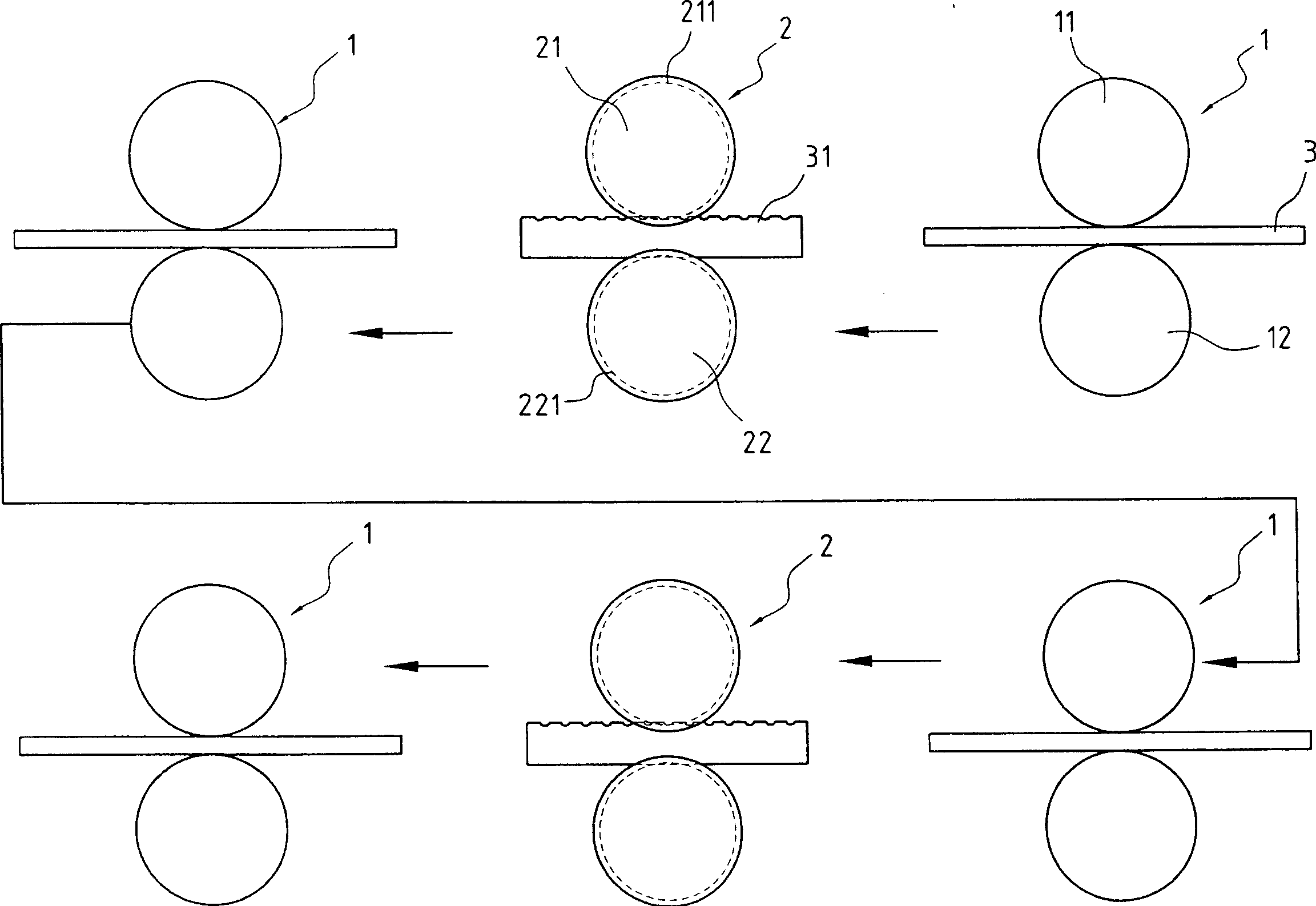
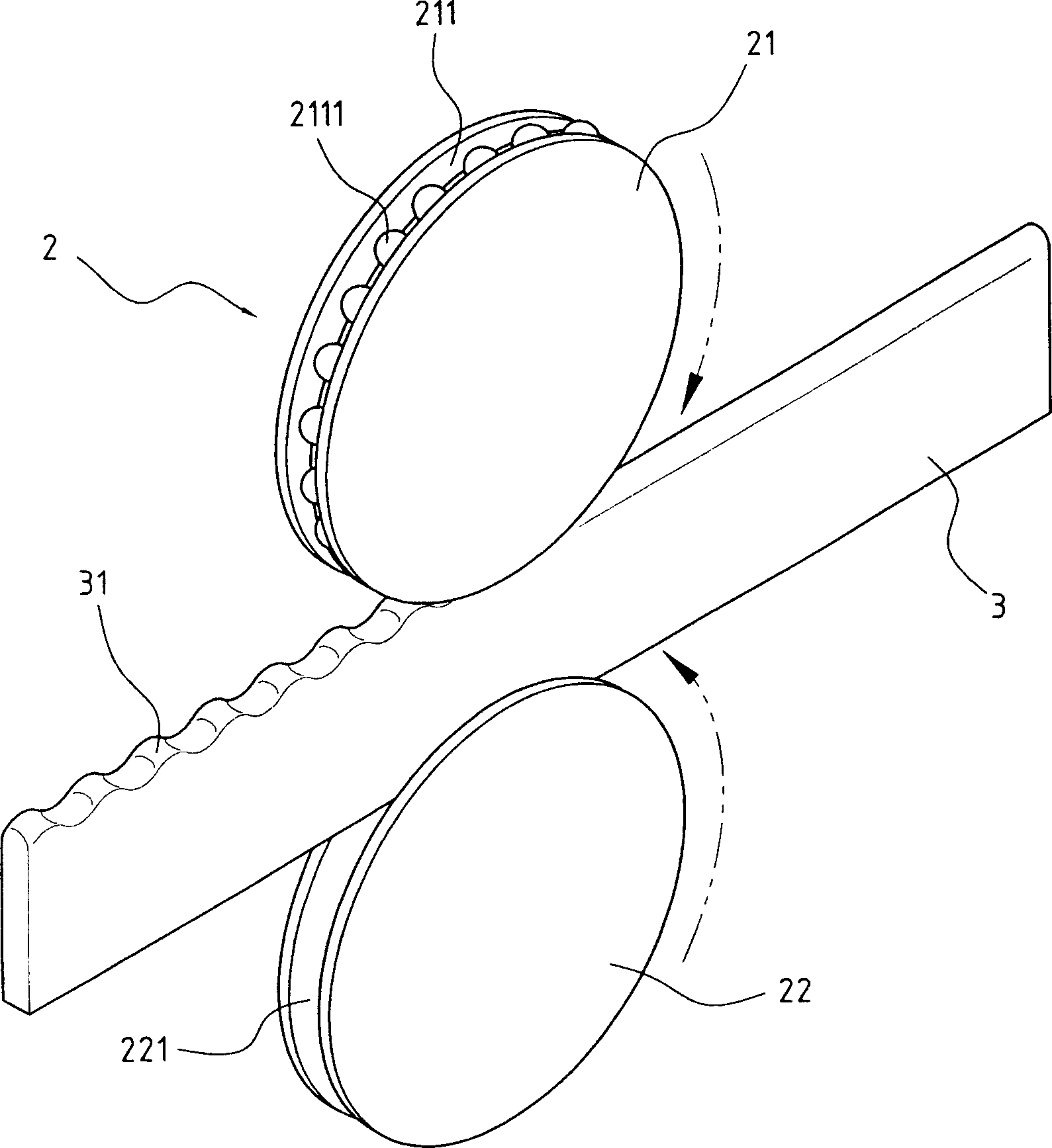
[0026] Such as figure 1 As shown, the first anti-slip iron manufacturing method and device provided by the present invention, its manufacturing process is that when the iron material 3 is heated to the working temperature, the iron material 3 is transported by means of conveying equipment (not shown in the figure) Through the calendering roller group 1 and calendering roller group 2 arranged at intervals in series, the iron material 3 is flattened horizontally by the calendering roller group 1 with a flat wheel surface, and then the iron material 3 is passed through the calendering roller group 2 The iron material 3 is guided by means of the annular grooves 211, 221 provided on the wheel surfaces of the upper and lower rollers 21, 22 of the calendering roller group 2, and the series of forming teeth 2111 arranged at the bottom of the annular groove 211 of the upper roller 21 are used to guide the iron material 3 One side of the iron material 3 is rolled to form protruding teet...


PUM


Abstract

A technology and apparatus for manufacturing the antiskid flat iron is disclosed. It features that the hot iron material at working temp passes through a series of calendering roller sets arranged at intervals and then a series of another calendering roller sets arranged at intervals. The first calendering roller has smooth or shaped surface for flattening or shaping the iron. The second calendering roller has ring slot on its surface for forming the convex teeth on the side edge of iron material.

Description

technical field [0001] The invention relates to a method and device for manufacturing a non-slip flat iron, which can efficiently manufacture the iron material by calendering to produce a non-slip flat iron with protruding teeth on one side and a flat other side In addition, the upper and lower edges of the center of the wide surface of the iron material are also pressed to a thickness ratio of 40% to 42% at the flat and convex parts, so that the iron material is formed into a non-slip I-type flat iron. Background technique [0002] At present, most of the gutter covers used to cover the gutter holes are welded with a plurality of flat irons to form a fence shape, so that rainwater can flow into the gutter from the fence-shaped gutter covers. It is known that the flat iron used to form the gutter cover is made by calendering, and each flat iron is made to be a vertical surface to form a high-strength gutter cover; the manufacturing method of the flat iron is to heat the iron...

Claims


Application Information

Patent Timeline
IPC IPC(8): B21D13/02E03F5/06
Inventor 洪伟彦
Owner CHIN STEEL & IRON
Features
  • R&D
  • Intellectual Property
  • Life Sciences
  • Materials
  • Tech Scout
  • Unparalleled Data Quality
  • Higher Quality Content
  • 60% Fewer Hallucinations
Learn More