Gyrotron and angular velocity sensor

A technology of vibrating gyroscope and vibrating body, which is applied in the direction of gyro effect for speed measurement, gyroscope/steering sensing equipment, instruments, etc., which can solve the problems of increasing the number of parts, increasing the cost, and complexity.

Inactive Publication Date: 2004-05-26
MURATA MFG CO LTD
View PDF3 Cites 9 Cited by
  • Summary
  • Abstract
  • Description
  • Claims
  • Application Information

AI Technical Summary

Problems solved by technology

However, when constructed in this way, there is a problem: only the long vibratory gyroscope equipped with the vibrator protrudes and is higher than other components on the mounting plate
In addition, although it has been considered to use a board that is separated from the main board and on which the vibrating gyro is mounted, and to generate a wire connection by using a flexible circuit board or the like, such a structure increases the number of parts and becomes complicated , resulting in an inevitable increase in cost

Method used


Image

  • Gyrotron and angular velocity sensor
  • Gyrotron and angular velocity sensor
  • Gyrotron and angular velocity sensor

Examples


Embodiment Construction

[0034] first preferred embodiment

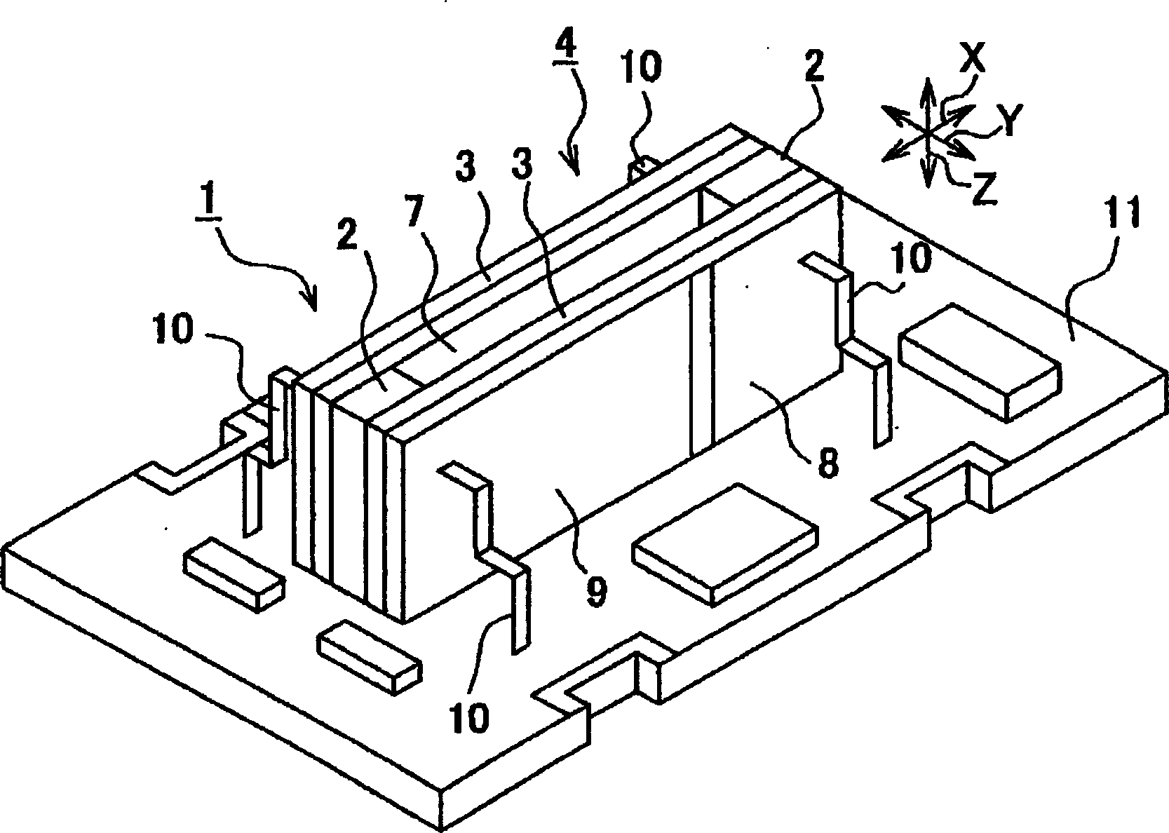
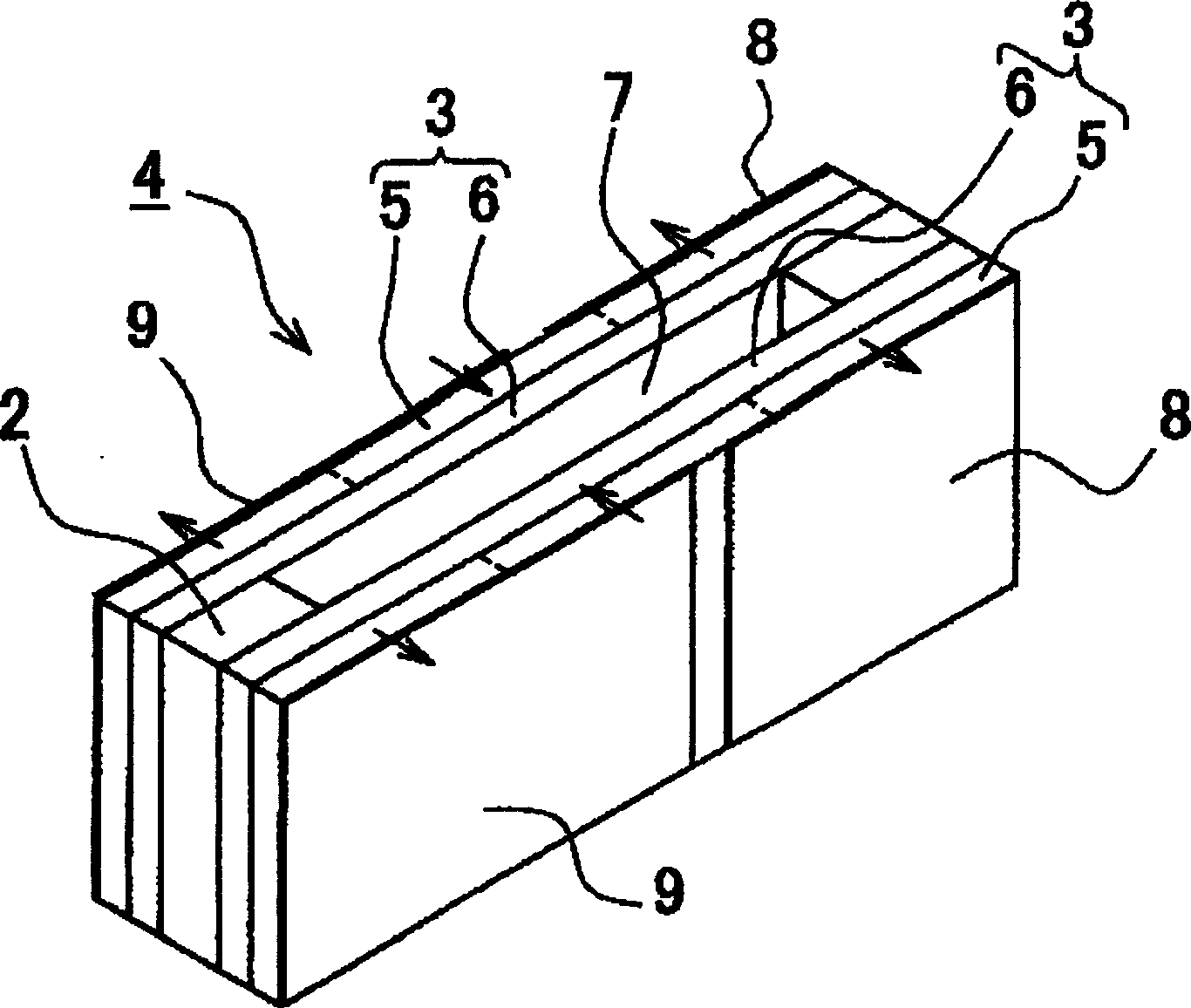
[0035] figure 1 is a perspective view of the entire structure of the vibrating gyroscope according to the first preferred embodiment of the present invention, figure 2 is a perspective view of the entire structure of the vibrator equipped with the vibrating gyroscope, image 3 is a schematic illustration of the structure of the main components of the vibratory gyroscope, including a drive detection circuit, and FIGS. 4A to 4C are top views diagrammatically showing the operation of the vibratory gyroscope, Figure 5 The relationship between the resonance frequency of buckling vibration and the resonance frequency of secondary bending vibration is shown.

[0036] also, Figures 6 to 10 The structures of the first to fourth modified examples of the vibrating gyroscope according to the first preferred embodiment are shown. also, Figure 11 The structure of the main parts of the angular velocity sensor constructed by using the vibrating gyr...


PUM


Abstract

A vibrating gyroscope includes a vibrator having a pair of vibrating bodies, both end portions in the longitudinal direction of which are fixed together in the thickness direction by intermediate parts and the vibrator is supported such that a secondary bending vibration with both ends free in the thickness direction of the vibrating bodies can be performed. The vibrating gyroscope also includes a driver for causing the vibrating bodies to perform buckling vibrations in opposite directions, and a detector for detecting the magnitude of the secondary bending vibration of the vibrator. The resonance frequency of the secondary bending vibration is close to the frequency of the buckling vibrations.

Description

technical field [0001] The present invention relates to a vibrating gyroscope and an angular velocity sensor, and more particularly to a structure of a vibrating gyroscope whose height is greatly reduced and a structure of an angular velocity sensor having the vibrating gyroscope. Background technique [0002] So far, in the navigation system and car body control system used in the car, since it is necessary to determine the yaw direction of the car, that is, the steering of the car body, the rotational angular velocity around the vertical axis perpendicular to the running surface (ground) to test. In order to detect rotational angular velocity, an angular velocity sensor equipped with a vibrating gyroscope generally including a pole vibrator or a tuning fork vibrator is used (see Japanese Unexamined Patent Application Publication No. 8-292033 and Japanese Unexamined Patent Application Publication No. 10-307029). [0003] In addition, the angular velocity sensor equipped w...

Claims


Application Information

Patent Timeline
Patent Type & Authority Applications(China)
IPC IPC(8): G01C19/56G01C19/5642G01C19/574
CPCG01C19/5642
Inventor 藤本克己
Owner MURATA MFG CO LTD
Why Eureka
Try Eureka