Supercharge Your Innovation With Domain-Expert AI Agents!

Anti bending moment structure having brace member and method thereof

A technology of supporting rods and bending moments, which is applied in the direction of building construction and construction, and can solve problems such as increased structural costs, enlarged rod sections, and increased structural weight

Inactive Publication Date: 2004-06-02
毛荦
View PDF3 Cites 4 Cited by
  • Summary
  • Abstract
  • Description
  • Claims
  • Application Information

AI Technical Summary

Problems solved by technology

However, there will be a small section in the beam that bears a very strong shear force, and the diagonal bracing will increase the cost of the structure and cause inconvenience in use
[0007] The current reinforced concrete structure deals with the large bending moment at both ends of the moment-resistant frame member, which is to arrange more steel bars at both ends of the member. However, too dense reinforcement will cause inconvenience in construction and affect the quality of construction.
In addition, the section of the rod must be increased, resulting in an increase in the self-weight of the structure, and the structure also takes up too much space

Method used


Image

  • Anti bending moment structure having brace member and method thereof
  • Anti bending moment structure having brace member and method thereof
  • Anti bending moment structure having brace member and method thereof

Examples


Embodiment Construction

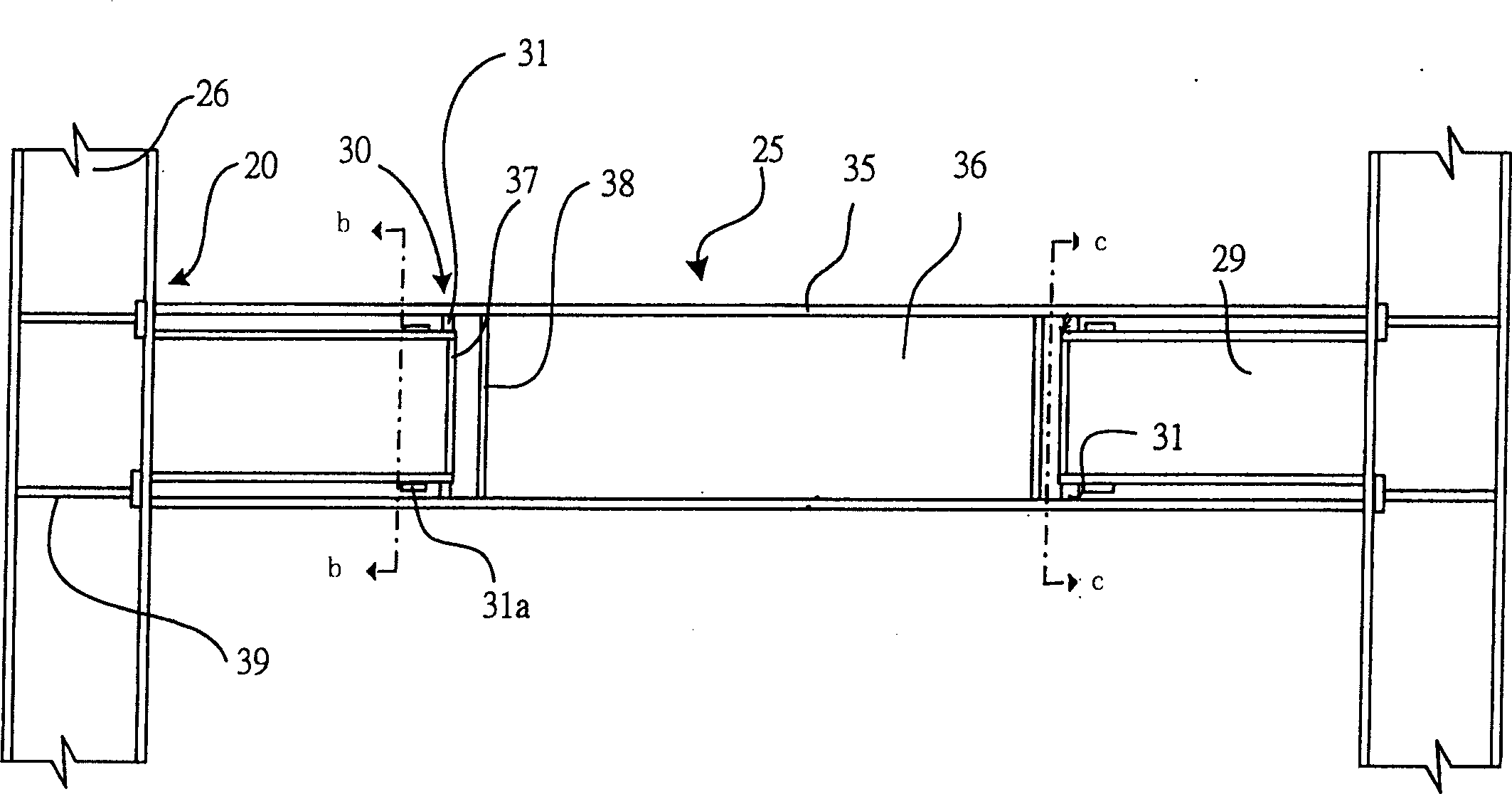
[0064] The present invention is a structure that strengthens the framework against bending moments with supporting rods. In the embodiment of Fig. 2, Fig. 2 (a) shows that the two ends of the H-shaped beam are supported by a pair of channel steel support rods 29 in the space on both sides of the web 36 between the upper and lower wings 35. Between the supported rod 25 and the supporting rod 29, a steel spacer 31 is used to transmit force at the support 30. The spacer 31 is welded to one of the supported rod 25 or the supporting rod 29, and not connected to the other rod. The reinforcing iron pieces 37 and 38 reinforce the supporting rod 29 and the supported rod 25 at the supporting position 30, and the reinforcing iron piece 39 reinforces the H-shaped steel column connection structure 26 at the bending moment joint position, so as to Transfer force to avoid local deformation caused by concentrated stress. Fig. 2 (b) is the sectional view of the b-b section in Fig. 2 (a), sho...


PUM


Abstract

The present invention is support rod structure and method for increasing bending resistance. Near the bending resistance joint, the support rod has one end attached to the supported rod and the other end combined with the connecting member together with the supported rod. When the structure bears load, the supported rod will be bent owing to the bending moment and the support rod and the supported rod will produce opposite forces to strengthen the bending resistance in the joint of the member. The said structure may be used in building, bridge, etc. in steel skeleton structure or reinforced concrete structure.

Description

technical field [0001] The invention relates to a moment-resisting structure, a supporting rod and a manufacturing method thereof, so as to enhance the moment-resisting performance of the structure. Background technique [0002] A structure composed of steel frames in which the members are joined in a manner capable of resisting bending moments. When the structure is subjected to lateral loads such as earthquake force and wind force, the bending moment is shown in Figure 1(a), or when the horizontal member is subjected to vertical load bending moment as shown in Figure 1(b), the member and other structural members such as connecting members or The foundation joint bears a larger bending moment than its vicinity. The usual method is to configure the rods according to the structural analysis results under various load combinations, and the design moment strength of the rods should exceed the bending moments generated under various load combinations. [0003] From the earthqu...

Claims


Application Information

Patent Timeline
Patent Type & Authority Applications(China)
IPC IPC(8): E04B1/19E04B1/38
Inventor 毛犖
Owner 毛荦
Features
  • R&D
  • Intellectual Property
  • Life Sciences
  • Materials
  • Tech Scout
  • Unparalleled Data Quality
  • Higher Quality Content
  • 60% Fewer Hallucinations
Learn More