Dynamic pressure bearing, mfg method and motor using same

A technology of dynamic pressure bearing and bearing seat, which is used in sliding contact bearings, rotating bearings, bearings, etc.

Active Publication Date: 2004-06-09
NIDEC CORP +1
View PDF2 Cites 3 Cited by
  • Summary
  • Abstract
  • Description
  • Claims
  • Application Information

AI Technical Summary

Problems solved by technology

[0013] An object of the present invention is to solve the above-mentioned problems due to the expansion deformation of the fixing surface of the outer circumference of the bearing housing, to ensure the stability of the fixed state between the bearing housing and the holding member, and to be able to obtain the required fixing strength

Method used


Image

  • Dynamic pressure bearing, mfg method and motor using same
  • Dynamic pressure bearing, mfg method and motor using same
  • Dynamic pressure bearing, mfg method and motor using same

Examples


Embodiment Construction

[0044] Embodiments of the present invention are described below.

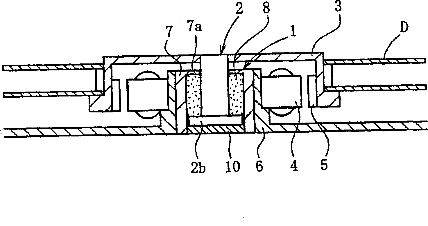
[0045] figure 1 An example of the structure of a spindle motor of an information processing apparatus equipped with the dynamic pressure bearing device 1 according to the present embodiment is shown. The spindle motor is used in a disk drive device such as an HDD, and includes a disk hub 3 serving as a rotor, a dynamic pressure bearing device 1 for supporting the disk hub 3 for rotation, and a thrust member for holding the disk hub 3 The bracket 6 of the pressure bearing device 1, as well as the stator 4 and the rotor magnet 5, are provided between the disk center 3 and the bracket 6 and are opposed to each other with a predetermined gap provided therebetween. In this embodiment, the disk center 3 is mounted on the shaft member 2 of the dynamic pressure bearing device 1 . The stator 4 is attached to the outer circumference of the bracket 6, the rotor magnet 5 is attached to the inner circumference of the disk...


PUM


Abstract

A securing surface of a housing comprises a deformation region, which deforms radially outward by a predetermined quantity during press fitting of a thrust member, and another region. The deformation region has a tapered shape that gradually reduces in diameter in the downward direction, and is receded radially inward relative to the other region of the securing surface, by an amount equivalent to the amount of outward deformation thereof during press fitting. When the thrust member is press fitted into the inner periphery of a press fitting portion of the housing, the securing surface of the housing becomes substantially straight along entire axial region L thereof.

Description

technical field [0001] The present invention relates to a dynamic pressure bearing device rotatably supported in a non-contact manner by the dynamic pressure action of lubricating oil generated in a bearing gap, its manufacturing method, and a motor using the bearing device Shaft element. The bearing unit is suitable for use in information processing equipment, including magnetic disc units such as HDD and FDD, optical disc units for CD-ROM, CD-R / RM, DVD-ROM / RAM, etc., and for MD, MO, etc. The spindle motor of a magneto-optical disk device, the multi-sided scanner motor in a laser beam printer (LBP), or a small motor for an electric device such as an axial fan. Background technique [0002] Among the various motors described above, performances such as high speed, low cost, and low noise generation are required in addition to high rotational accuracy. One of the structural components that determine these performance requirements is the bearings that support the motor shaft...

Claims


Application Information

Patent Timeline
Patent Type & Authority Applications(China)
IPC IPC(8): F16C17/02F16C17/04F16C17/26F16C33/10F16C33/74G11B19/20
CPCG11B19/2009F16C33/74F16C33/107F16C17/26F16C17/107F16C2370/12F16C17/04F16C17/02F16C33/104
Inventor 玉冈健人中岛良一栗村哲弥
Owner NIDEC CORP
Why Eureka
Try Eureka