Eureka AIR delivers breakthrough ideas for toughest innovation challenges, trusted by R&D personnel around the world.

Continuous constant-pressure synchronous grouting device for shield tunnel construction

A technology of synchronous grouting and shield tunneling, which is applied in the direction of tunnels, tunnel linings, cement mixing devices, etc., can solve problems such as inability to be synchronized tightly, complex structures, and external protruding obstructions, and achieve the effect of improving efficiency

Pending Publication Date: 2021-11-05
CHINA CONSTR FOURTH ENG DIV
View PDF3 Cites 2 Cited by
  • Summary
  • Abstract
  • Description
  • Claims
  • Application Information

AI Technical Summary

Problems solved by technology

Although this device realizes the synchronous grouting reinforcement in the shield tunneling process, in addition, other existing synchronous grouting devices such as CN211715136UZ need to realize the free circulation of the internal slurry by means of a grouting tank and an air pressure device, and CN101298836A relates to a The pressure balance device used for the start of the shield machine applies air pressure to the front of the cutter head to balance the excavation surface, the sealing mechanism firmly seals the earth pressure and water pressure in front of the shield machine, and the shield machine continues to move forward. When the segments are assembled in the pressurized balance device, the synchronous grouting is started, and the grout is sealed by the end cover, but the following problems still exist: the device pushes the mud through the pressurized air pipe, and the structure is complicated. When there is less mud, the internal The air is circulated, the pushing effect is poor, and the inner wall is stuck with mud. At the same time, when the mud is poured into the gap, it cannot be synchronized tightly, resulting in external protrusions and obstructions.

Method used


Image

  • Continuous constant-pressure synchronous grouting device for shield tunnel construction
  • Continuous constant-pressure synchronous grouting device for shield tunnel construction
  • Continuous constant-pressure synchronous grouting device for shield tunnel construction

Examples


Embodiment Construction

[0023] In describing the present invention, it should be understood that the terms "center", "longitudinal", "transverse", "length", "width", "thickness", "upper", "lower", "front", " Orientation indicated by rear, left, right, vertical, horizontal, top, bottom, inside, outside, clockwise, counterclockwise, etc. The positional relationship is based on the orientation or positional relationship shown in the drawings, and is only for the convenience of describing the present invention and simplifying the description, rather than indicating or implying that the referred device or element must have a specific orientation, be constructed and operated in a specific orientation, Therefore, it should not be construed as limiting the invention.

[0024] In the description of the present invention, "plurality" means two or more, unless otherwise specifically defined.

[0025] In the description of the present invention, it should be noted that, unless otherwise specified and limited, t...


PUM


Abstract

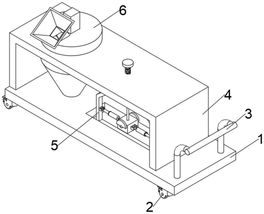
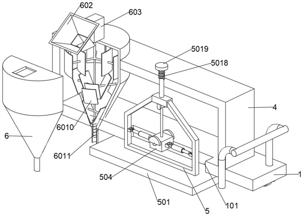
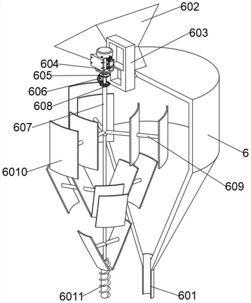
The invention discloses a continuous constant-pressure synchronous grouting device for shield tunnel construction, and belongs to the technical field of shield tunnel construction. The continuous constant-pressure synchronous grouting device for shield tunnel construction comprises a moving plate, a conical grouting barrel is arranged on the front side of a U-shaped frame, and the lower end of the conical grouting barrel penetrates through the interior of the moving plate, extends to the exterior and communicates with a discharging hole; the lower end of a sleeve penetrates through the inner wall of a machine box, extends into the conical grouting barrel and is annularly provided with stirring rods at equal intervals; arc-shaped plates are arranged on the circumferential outer wall of the stirring rods in a front-and-back structure; an output shaft of a motor B penetrates through the interior of the sleeve to extend to the exterior and is coaxially connected with an auger, through close fit of the structures, after slurry is stirred by the device, extrusion conveying can be carried out at the same time, the situation that when a small amount of slurry is pushed through a pressurization air pipe, pushing cannot be achieved due to internal air circulation is avoided, and the working efficiency is improved; and meanwhile, slurry on the inner wall can be scraped out through the arc-shaped plates, and the situation that the slurry is solidified due to the fact that the slurry is difficult to clean is avoided.

Description

technical field [0001] The invention relates to the technical field of shield tunnel construction, in particular to a continuous constant pressure synchronous grouting device for shield tunnel construction. Background technique [0002] During the construction of the shield tunnel, the outer diameter of the cutter head of the shield machine is larger than the outer diameter of the shield tunnel, so when the shield tunnel escapes from the tail of the shield, a gap of a certain thickness will be formed between the shield tunnel and the ground. The gap needs to be filled with synchronous grouting material to prevent excessive displacement of the surrounding soil in the direction of the shield tunnel and increase the disturbance to the surrounding strata, and at the same time prevent excessive settlement and deformation of the ground surface. The prior art publication No. CN111005731A provides a continuous constant pressure synchronous grouting device for shield tunnel construct...

Claims


Application Information

Patent Timeline
Patent Type & Authority Applications(China)
IPC IPC(8): E21D11/10B28C5/16B08B1/04
CPCE21D11/105E21D11/10B28C5/16B28C5/0831B28C5/0862B08B1/165B08B1/32
Inventor 张宝刚王军华麻歆陈晓军王立家
Owner CHINA CONSTR FOURTH ENG DIV
Why Eureka
Eureka Blog
Learn More