Universal battery charger

A battery charger, battery voltage detection technology, applied in battery circuit devices, current collectors, electric vehicles, etc., can solve problems such as switch circuit damage

Inactive Publication Date: 2004-06-16
KOKI HLDG CO LTD
View PDF0 Cites 10 Cited by
  • Summary
  • Abstract
  • Description
  • Claims
  • Application Information

AI Technical Summary

Problems solved by technology

This may cause serious damage to the switching circuit in the charging circuit

Method used


Image

  • Universal battery charger
  • Universal battery charger
  • Universal battery charger

Examples


Embodiment Construction

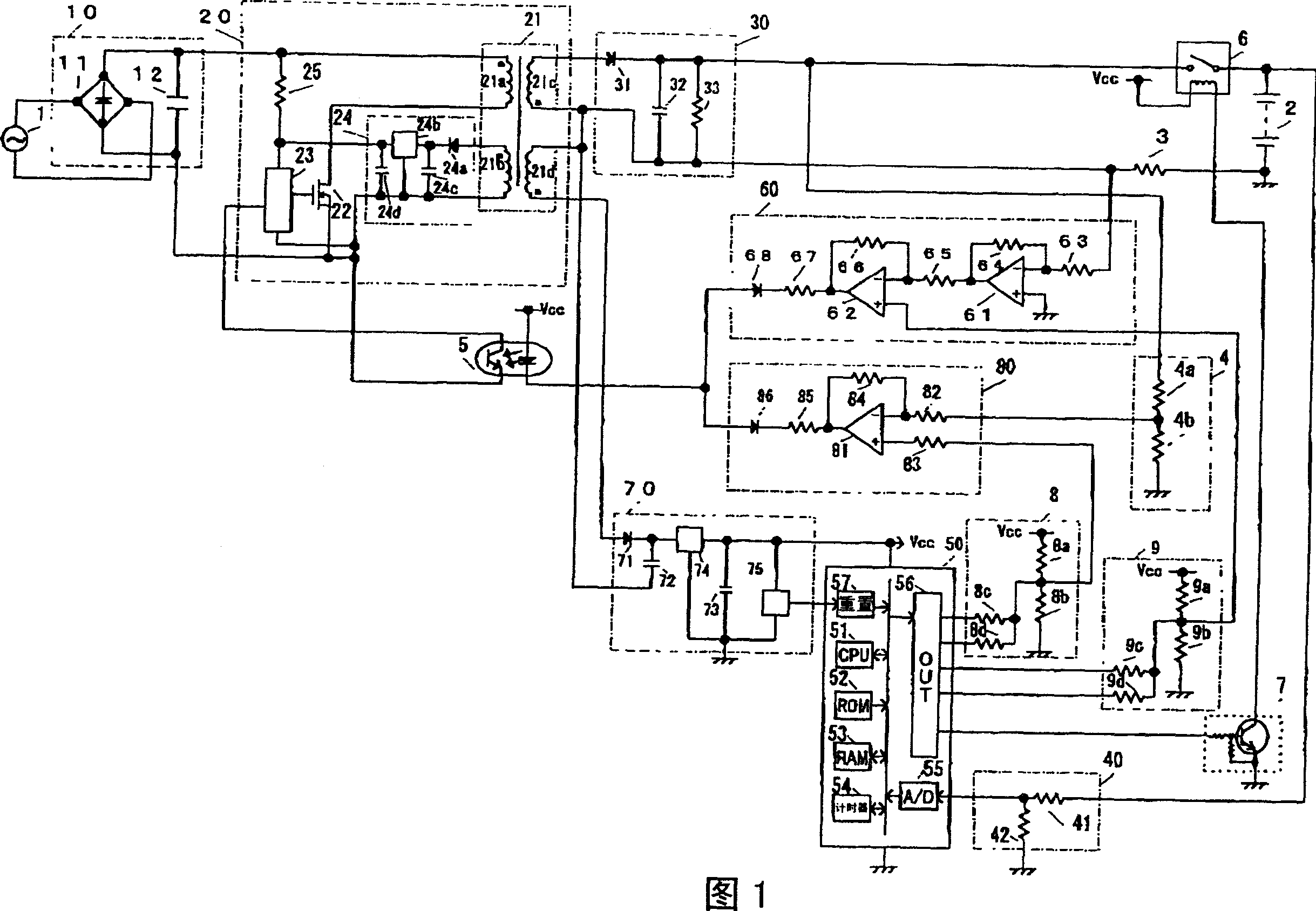
[0012] A universal battery charger according to a preferred embodiment of the present invention will be described below with reference to the accompanying drawings. FIG. 1 is a schematic diagram showing the structure of a general-purpose battery charger. In use, the battery charger is connected to an AC power source 1 and a battery 2 is loaded into the battery charger. The battery 2 is composed of a plurality of single cells connected in series.

[0013] The battery charger includes a switch circuit 6 and a switch drive circuit 7 . The switch circuit 6 is inserted on the charging current path, that is, between the rectification / smoothing circuit 30 and the battery 2 . The switch circuit 6 is configured by a relay, which turns on the switch when the charging current is supplied to the battery 2, and stops charging the battery 2 when the battery 2 is removed from the battery charger, or when a fully charged state of the battery 2 is detected In the case of , when the charging...


PUM


Abstract

Provided is a universal battery charger with low power consumption during a standby condition and a rush current suppressing capability at the time of commencement of charging, a voltage slightly larger than a battery voltage is produced and applied to the battery. Thereafter, the highest voltage is produced and applied to the battery to charge the same. When the battery is unloaded from the battery charger, the lowest voltage is produced to save power consumption.

Description

technical field [0001] The present invention relates to a universal battery charger capable of charging batteries at different voltages. Background technique [0002] Among various types of battery chargers, a general-purpose battery charger capable of charging batteries composed of different numbers of single cells, that is, batteries with different voltages, has become more and more popular. Universal battery chargers can charge batteries such as 9.6V, 12V and 14V batteries consisting of 8, 10 and 12 cells in series, respectively, where each cell is 1.2V. [0003] The voltage output from a general-purpose battery charger is under constant voltage control, and the battery charger is set so that it outputs the voltage required to charge a battery consisting of the maximum number of cells that the battery charger can handle. Problems arise when charging batteries consisting of fewer than the maximum number of cells. As a result, when the switching circuit is closed, a large...

Claims


Application Information

Patent Timeline
Patent Type & Authority Applications(China)
IPC IPC(8): H02J7/10H02J7/00H02J9/00
CPCH02J7/0065H02J9/005H02J2207/20Y04S20/20Y02B70/30
Inventor 高野信宏船桥一彦
Owner KOKI HLDG CO LTD
Why Eureka
Try Eureka