A distributed fault-locating method in a total optical network

A fault location and distributed technology, applied in transmission monitoring/testing/fault measurement system, electromagnetic wave transmission system, electrical components, etc. Classification problems, to overcome the long time for fault location, avoid repetitive actions, and enhance the effect of modularization

Inactive Publication Date: 2004-06-16
ZTE CORP +1
View PDF0 Cites 32 Cited by
  • Summary
  • Abstract
  • Description
  • Claims
  • Application Information

AI Technical Summary

Problems solved by technology

[0014] The purpose of the present invention is to overcome the shortcomings in the prior art of long fault location time, poor realizability, no distinction between resources and services, large amount of signaling transmission between nodes during the fault location process, and unclear fault location and protection recovery functions , a distributed fault location method in all-optical networks is proposed

Method used


Image

  • A distributed fault-locating method in a total optical network
  • A distributed fault-locating method in a total optical network
  • A distributed fault-locating method in a total optical network

Examples


Embodiment Construction

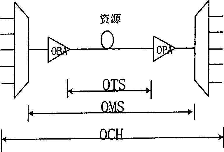
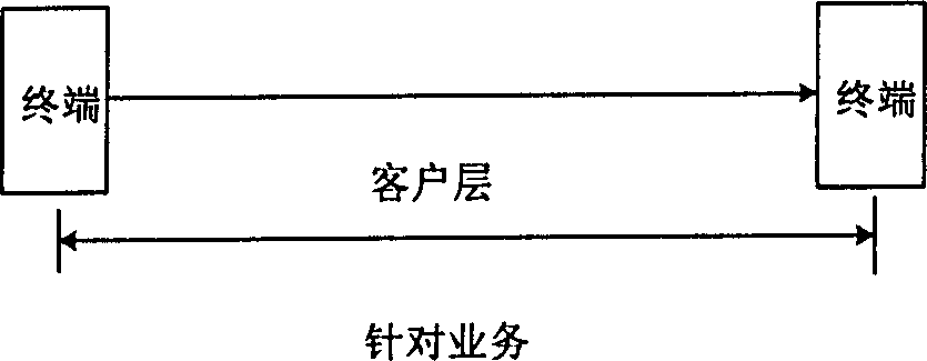
[0043] From the distributed fault location method described in the technical solution of the present invention, it can be seen that the fault monitoring point in the optical node needs to be set, and for the setting of the fault monitoring point, such as figure 1 As shown, the resources of the optical network correspond to three layers of OTS layer (transmission section layer), OMS layer (multiplex section layer), OCH layer (optical channel layer), and the client layer corresponds to specific end-to-end services (such as figure 2 ).

[0044] The same customer can occupy different resources, and the same resource can carry different customers. Resources are the carriers of customers. The ultimate purpose of protection and recovery is to protect and recover customer information, but these protection and recovery actions need to be completed through resources. Traditional The method does not separate resources and services, which makes the functions of fault location and protect...


PUM


Abstract

The invention discloses a distributed fault positioning method in all-optical network, dividing fault position into resource fault position and service fault position, and each optical node in optical network positions its own adjacent resource fault monitoring point in a distributed mode. The method's steps: A, collect warning information in the place of each monitoring point; B, separate warning information belonging to the same link and path from different monitoring points to make relativity processing; C, filter warning information D, position concrete resource fault; F, position service fault. The separation of resource and service helps to protect resource and resume service, avoid repeated action. It reduces signaling transmission quantity between nodes during positioning fault.

Description

technical field [0001] The invention relates to optical fiber communication, more specifically to a distributed fault location method in an all-optical network. Background technique [0002] Fault location is the basis of network survivability. Neither network protection nor network restoration can be separated from fault location. Even network optimization configuration cannot be separated from network fault location information. Given the importance of fault localization in networks, fault localization has been extensively studied. [0003] Typical fault locations include: [0004] manual testing [0005] This method is to manually determine the specific location of the fault in the event of a fault. It can be seen that this method is not suitable for large-scale networks, and cannot protect damaged services in real time. The main purpose is management and maintenance. [0006] channel correlation analysis [0007] The principle of this method is to use the correlation...

Claims


Application Information

Patent Timeline
Patent Type & Authority Applications(China)
IPC IPC(8): H04B10/07
Inventor 赵勇王健全施社平陈宝忠顾畹仪
Owner ZTE CORP
Why Eureka
Try Eureka