
Refrigerator using double-suction centrifugal fan

A technology of centrifugal fans and refrigerators, which is applied in the direction of household refrigerators, appliances, coolers, etc., and can solve the problems of decreased utilization rate of heat transfer area and decreased heat transfer effect of evaporator 3a

Inactive Publication Date: 2004-06-23
LG ELECTRONICS INC
View PDF0 Cites 8 Cited by
  • Summary
  • Abstract
  • Description
  • Claims
  • Application Information

AI Technical Summary

Problems solved by technology

Therefore, the utilization rate of the heat transfer area of ​​the evaporator 3a decreases, and the heat transfer effect decreases

Method used


Image

  • Refrigerator using double-suction centrifugal fan
  • Refrigerator using double-suction centrifugal fan
  • Refrigerator using double-suction centrifugal fan

Examples


Embodiment Construction

[0027] The invention will be described in detail with reference to the preferred embodiments of the invention and illustrated by way of example in the accompanying drawings. The same reference numerals in the figures indicate the same or similar parts.

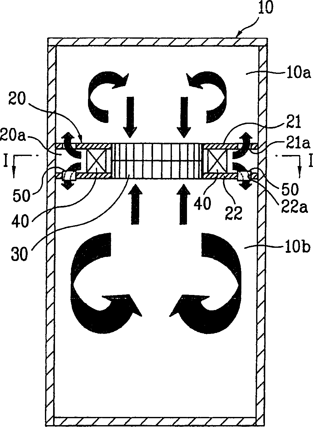
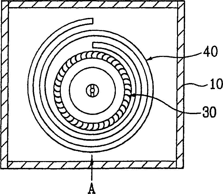
[0028] figure 2 is a schematic diagram of a first embodiment of a refrigerator according to the present invention, image 3 is along figure 2 The cross-sectional view of the I-I section line.

[0029] Next, a first embodiment of the present invention will be explained in detail. The refrigerator according to the present invention includes a box body 10, a frame 20, a double-suction centrifugal fan 30, and outlets 21a and 21b.

[0030] Such as figure 2 with image 3 As shown, there is a storage space in the box body, and the frame 20 separates the box body into a freezer compartment 10a and a refrigerator compartment 10b. The frame 20 is formed of double partitions, including an upper panel 21 and a lower panel 22 . ...


PUM


Abstract

This invention is to increase a floor area ratio of a freezing chamber and a utilization rate of heat transfer. A refrigerator is disclosed, which includes a cabinet having a storage space, a mullion provided in the cabinet to divide the storage space into a freezing chamber and a refrigerator chamber, the mullion having a cold airflow passage provided therein that is communicated with the freezing chamber and the refrigerator chamber, a double suction centrifugal blower provided in a middle space of the mullion and sucking air from the freezing chamber and the refrigerator chamber and exhausting to the cold airflow passage, an evaporator provided in the cold airflow passage for exchanging heat with the air exhausted from the double suction centrifugal blower, a top outlet and a bottom outlet exhausting air being passed through the evaporator to the freezing chamber and the refrigerator chamber.

Description

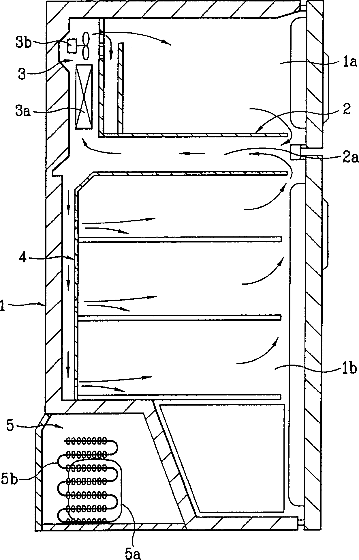
technical field [0001] The invention relates to a refrigerator, in particular to a refrigerator using a double-suction centrifugal fan. Background technique [0002] Generally, a refrigerator is a device that can keep stored food fresh for a long time. Such as figure 1 The illustrated refrigerator includes an evaporation chamber 3 having a cabinet 1, a frame 2, an evaporator 3a, and a fan 3b, and an equipment room accommodating refrigerant pipes, a compressor, and a condenser. [0003] The composition of the refrigerator is explained below, and there is a storage space in the cabinet 1 . The frame 2 divides the storage space in the box into a freezer compartment 1a and a refrigerator compartment 1b. There is a cold air passage on the frame 2, which can make the refrigerant flow between the freezing chamber 1a and the refrigerating chamber 1b. The refrigerant pipe 4 connected to the cold air passage 2a transmits the refrigerant to each part of the refrigerating chamber 1b...

Claims


Application Information

Patent Timeline
Patent Type & Authority Applications(China)
IPC IPC(8): F25D17/04F25D17/06
CPCF25D2317/0653F25D2400/04F25D17/045F25D2317/0681F25D17/065F25D2317/0683F25D2317/0664F25D17/06
Inventor 李翔旭
Owner LG ELECTRONICS INC
Learn More