Magnetron and microwave oven and high-frequency heating equipment equiped with the same magnetron

A magnetron and high-frequency technology, applied in the field of microwave ovens and high-frequency heating equipment, can solve the problems of increasing the weight and manufacturing cost of the magnetron, reducing the oscillation efficiency of the magnetron, and achieving the effect of reducing costs

Inactive Publication Date: 2004-06-23
SAMSUNG ELECTRONICS CO LTD
View PDF0 Cites 4 Cited by
  • Summary
  • Abstract
  • Description
  • Claims
  • Application Information

AI Technical Summary

Problems solved by technology

Then, the permanent magnet is demagnetized due to the heating of the permanent magnet, and the size of the magnetron is increased for the reason of the decrease of the oscillation efficiency, which reduces the oscillation efficiency of the magnetron and increases the magnetron, respectively. Weight and Manufacturing Cost

Method used


Image

  • Magnetron and microwave oven and high-frequency heating equipment equiped with the same magnetron
  • Magnetron and microwave oven and high-frequency heating equipment equiped with the same magnetron
  • Magnetron and microwave oven and high-frequency heating equipment equiped with the same magnetron

Examples


Embodiment Construction

[0042] Specific embodiments of the present invention will now be described in detail, specific examples of which are shown in accompanying drawings, wherein like numerals indicate like parts. The embodiments will be described below in order to explain the invention by referring to the figures. Not only that, but for simplicity of illustration, the direction of rotation of the magnetic flux due to the polarization of the North and South poles is ignored.

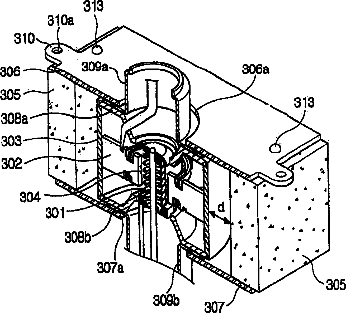
[0043] image 3 is the longitudinal section of the main part of the magnetron according to the embodiment of the present invention. exist image 3 Among them, the ring-shaped anode includes many blades forming a resonant circuit and the anode cylinder 303, the cathode including the filament 301 that releases thermions at high temperature is located in the center of the axis of the anode, and the thermion group moves in it under the influence of the electric and magnetic fields An active / predetermined space is formed betwee...


PUM


Abstract

A magnetron includes a ring-shaped anode, a cathode, an activating space, at least one permanent magnet and a magnetic flux carrying unit. The ring-shaped anode forms a plurality of resonance circuits. The cathode is disposed at the axial center of the anode to emit thermions. The activating space is formed between the anode and the cathode. The at least one permanent magnet is provided beside the anode. The magnetic flux carrying unit carries magnetic flux generated by the at least one permanent magnet to the activating space. A microwave oven and / or high frequency heating apparatus may utilize the magnetron.

Description

technical field [0001] The present invention generally relates to magnetrons, microwave ovens and high-frequency heating equipment equipped with magnetrons, and in particular to improvements in the arrangement of magnets for applying magnetic flux in their activation spaces and changes in the shape of the upper and lower yokes corresponding to the arrangement improvements Magnetrons and microwave ovens and high-frequency heating equipment equipped with such magnetrons. Background technique [0002] The conventional magnetron structure is illustrated in the accompanying drawings. like figure 1 As shown, in a conventional magnetron, a plurality of vanes 102 forming an anode and an anode cylinder 101 are arranged at regular intervals along the radial direction to form a resonant circuit. The antenna 103 is connected to one of the blades 102 and transmits harmonics to the outside, and the blades 102 are connected alternately through two pairs of strip rings 108 . Also, a cath...

Claims


Application Information

Patent Timeline
Patent Type & Authority Applications(China)
IPC IPC(8): H05H7/02F24C7/02G01S7/282H01J23/10H01J23/15H01J25/50H01J25/587H05B6/64H05B6/66H05B6/72
CPCH05B6/72H01J23/10H01J25/587H01J23/15
Inventor 孙钟哲博里什·V·拉伊斯基河现竣
Owner SAMSUNG ELECTRONICS CO LTD
Why Eureka
Try Eureka