Rotary brush device and dust cleaner using same

A technology of rotating brushes and vacuum cleaners, applied in the directions of vacuum cleaners, suction nozzles, applications, etc., can solve the problems that the rotating force mechanism occupies a large space, restricts the miniaturization of equipment, and is not ideal for use and operation.

Inactive Publication Date: 2004-06-30
PANASONIC CORP
View PDF1 Cites 7 Cited by
  • Summary
  • Abstract
  • Description
  • Claims
  • Application Information

AI Technical Summary

Problems solved by technology

[0004] However, in such a conventional structure, the mechanism for transmitting rotational force occupies a large space, which limits the miniaturization and weight reduction of the equipment, and is not ideal for use and operation.

Method used


Image

  • Rotary brush device and dust cleaner using same
  • Rotary brush device and dust cleaner using same
  • Rotary brush device and dust cleaner using same

Examples


Embodiment Construction

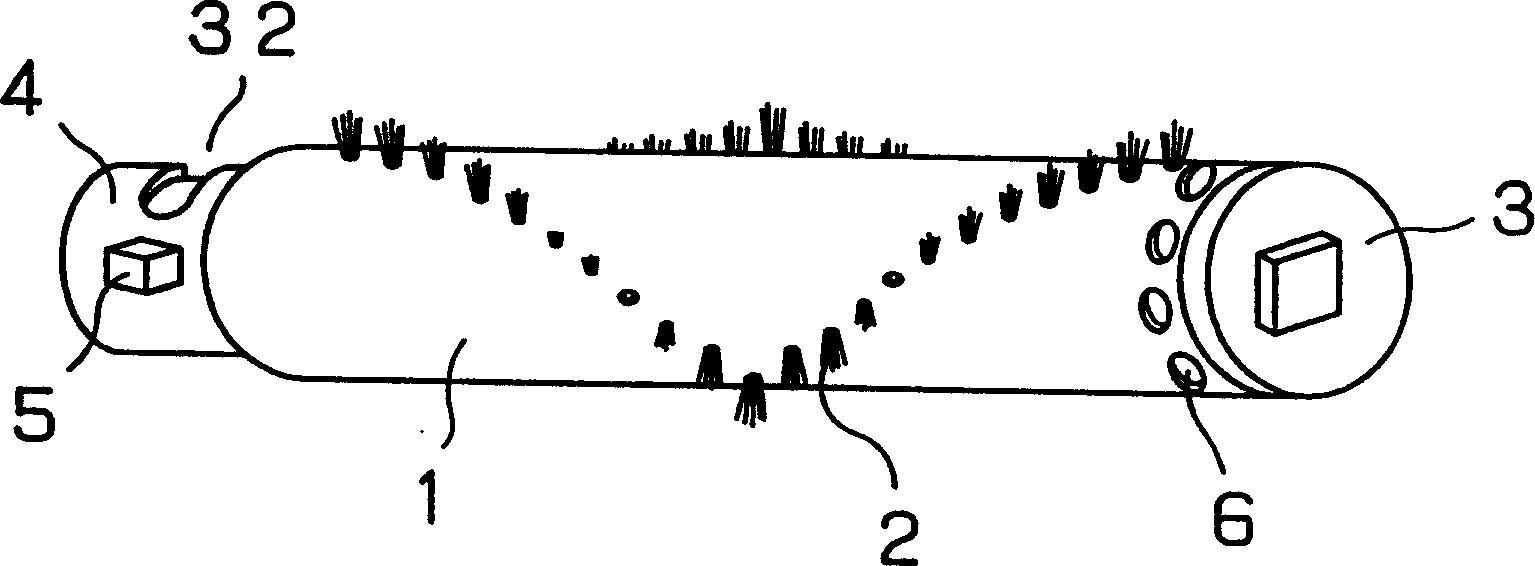
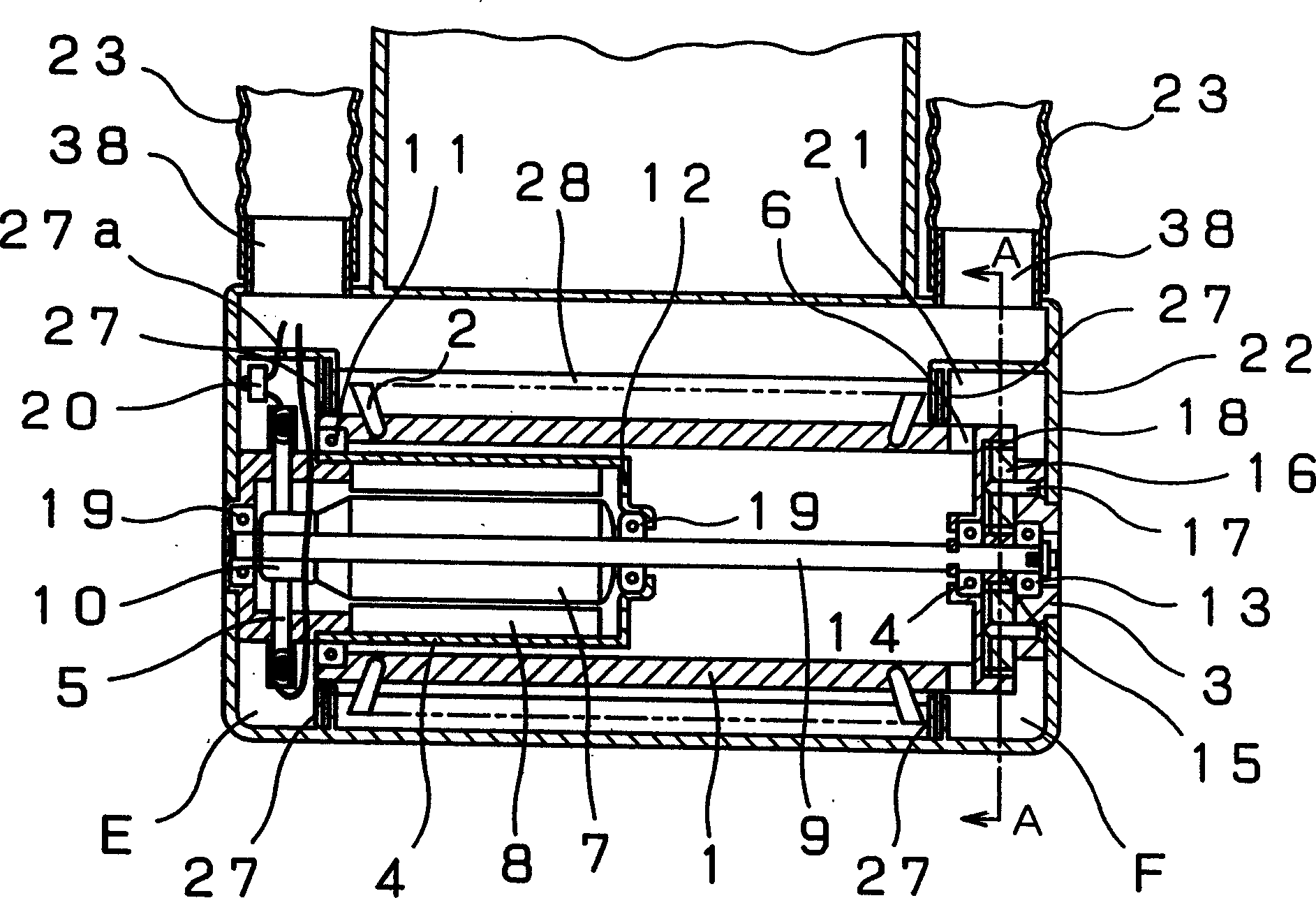
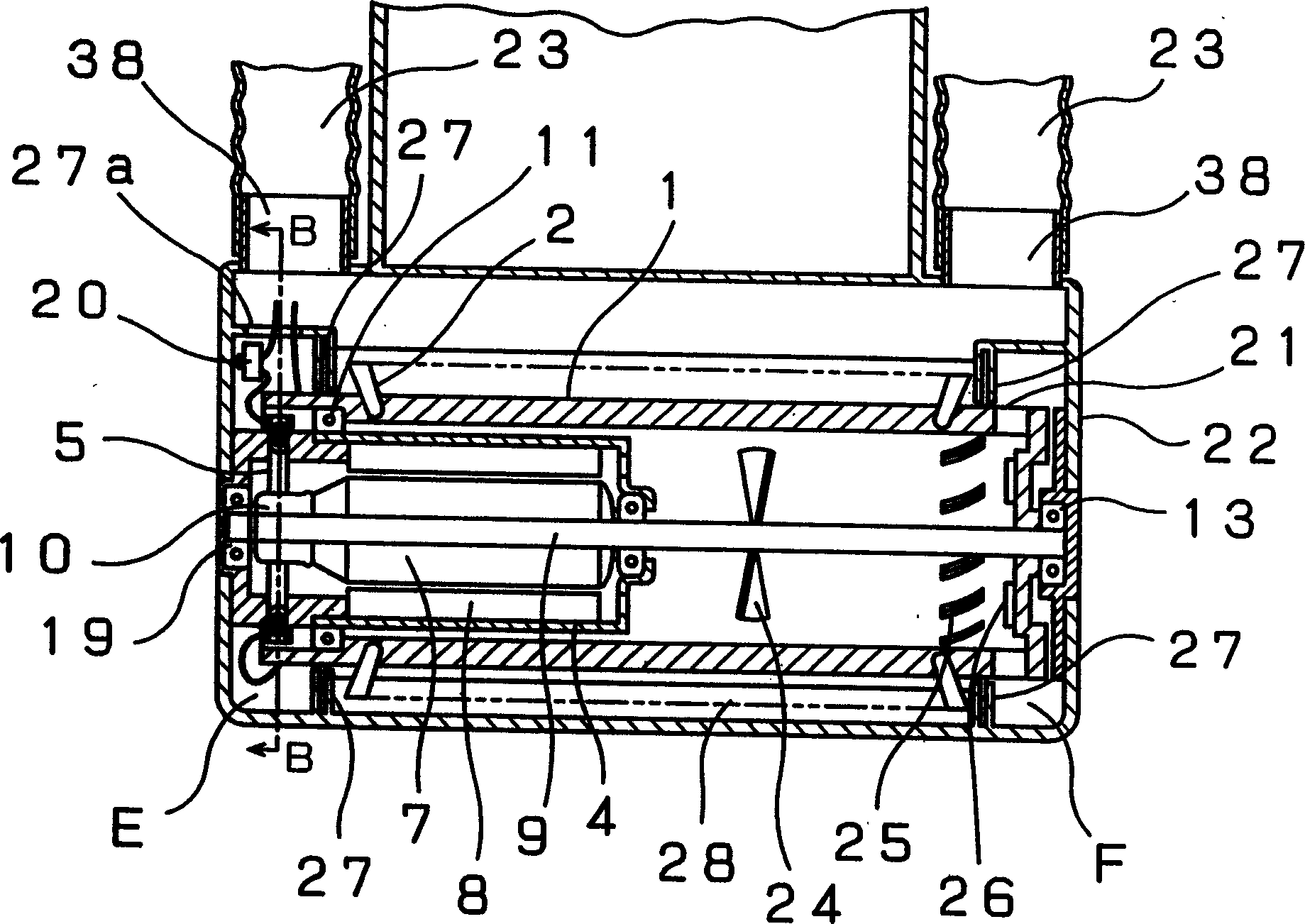
[0025] Embodiments of the present invention will be described below using the drawings. figure 1 Among them, 1 is a cylindrical body, and 2 is a brush in which bristles are planted in a V shape on the outer peripheral surface of the cylindrical body 1, and these two constitute a rotating brush. In addition, depending on the purpose and use, instead of a brush shape, a thin plate-shaped stirring material, a wiper, or the like may be used. In addition, a rotating brush can also be formed by appropriately combining a brush-shaped stirring member, a thin-plate-shaped stirring member, and a wiping member. 3 is a reduction gear frame constituting a reduction mechanism, 4 is a motor frame supporting a motor installed in the cylindrical body 1, 5 is a carbon brush, and 6 is a first opening, which is provided on the outer periphery of the cylindrical body 1 for ventilation. through hole. The first opening 6 is formed on the end peripheral surface of the cylindrical body 1, and is pro...


PUM


Abstract

A motor is incorporated in a cylindrical body which is a rotary brush. Rotation of a rotor of the motor, directly or via a speed reduction mechanism, drives the rotary brush. Cooling air runs through the cylindrical body so that the motor is cooled and protected. A rotary brush and an electric apparatus using this rotary brush can be therewith reduced in size.

Description

[0001] The present invention is a divisional application of the No. 99104798.2 patent application filed on April 2, 1999, entitled "Rotating Brush Device and Electrical Equipment Using the Device". technical field [0002] The present invention relates to a rotary brush device used in a vacuum cleaner and the like, and a vacuum cleaner using the same. Background technique [0003] The rotating brush device used in the conventional upright vacuum cleaner is driven by the motor installed in the main body of the vacuum cleaner to drive the electric blower for suction through a belt and gears to drive the rotating brush installed in the floor suction nozzle, or it is used separately in the floor suction nozzle. The rotating brush is driven by a motor from the outside of the rotating brush. [0004] However, in such a conventional structure, the mechanism for transmitting the rotational force occupies a large space, which limits the miniaturization and weight reduction of the equ...

Claims


Application Information

Patent Timeline
Patent Type & Authority Applications(China)
IPC IPC(8): A47L9/00A47L5/28A47L5/30A47L9/02A47L9/04A47L9/28
CPCA47L5/30A47L9/0411A47L9/2857A47L9/0477A47L9/0455A47L9/281A47L9/2842A47L9/2821A47L5/28A47L9/02A47L9/2889A47L9/2831A47L9/0438A47L9/2826A47L9/2805A47L9/2847A47L9/04
Inventor 西村博史林精造
Owner PANASONIC CORP
Why Eureka
Try Eureka