
Clamp for laser cutting

A laser cutting and special fixture technology, which is applied in welding/cutting auxiliary equipment, manufacturing tools, metal processing equipment, etc., can solve the problems of laser cutting machine rotating parts crashing, damage to the life of the laser cutting machine, and complex stress distribution of the workpiece

Inactive Publication Date: 2004-06-30
HUAZHONG UNIV OF SCI & TECH
View PDF0 Cites 9 Cited by
  • Summary
  • Abstract
  • Description
  • Claims
  • Application Information

AI Technical Summary

Problems solved by technology

This kind of fixture is too rigid, on the one hand, there is no release space for the deformation of the workpiece, on the other hand, the stress distribution inside the workpiece is more complicated, it is difficult to find the law, and it is difficult to make corresponding adjustments to the workpiece
Therefore, after processing some pipes in sections, due to the local bending and deformation of the pipes, the torque required for pipe rotation increases rapidly, which can easily cause the rotation parts of the laser cutting machine to crash, which greatly damages the life of the laser cutting machine

Method used


Image

  • Clamp for laser cutting
  • Clamp for laser cutting
  • Clamp for laser cutting

Examples


Embodiment Construction

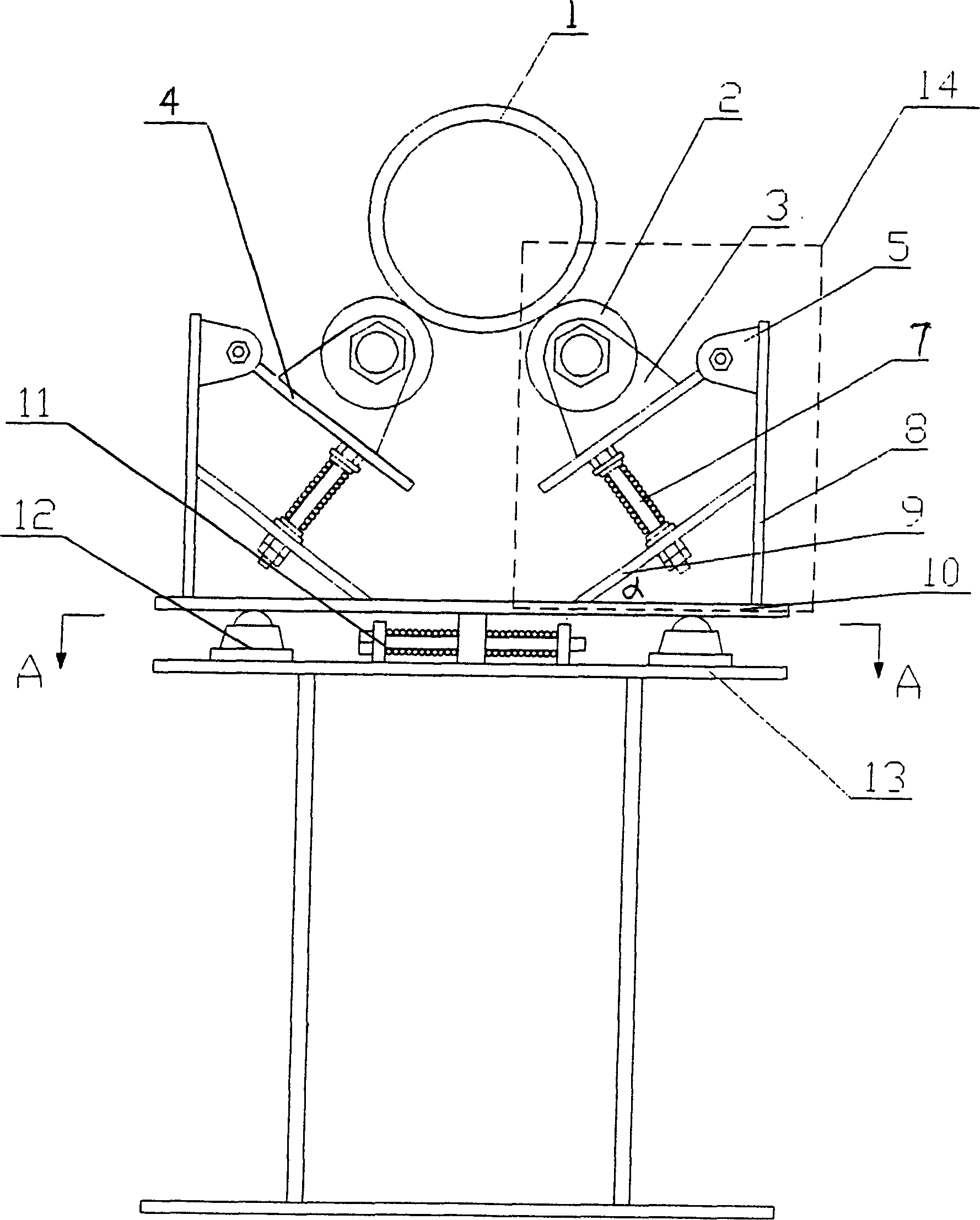
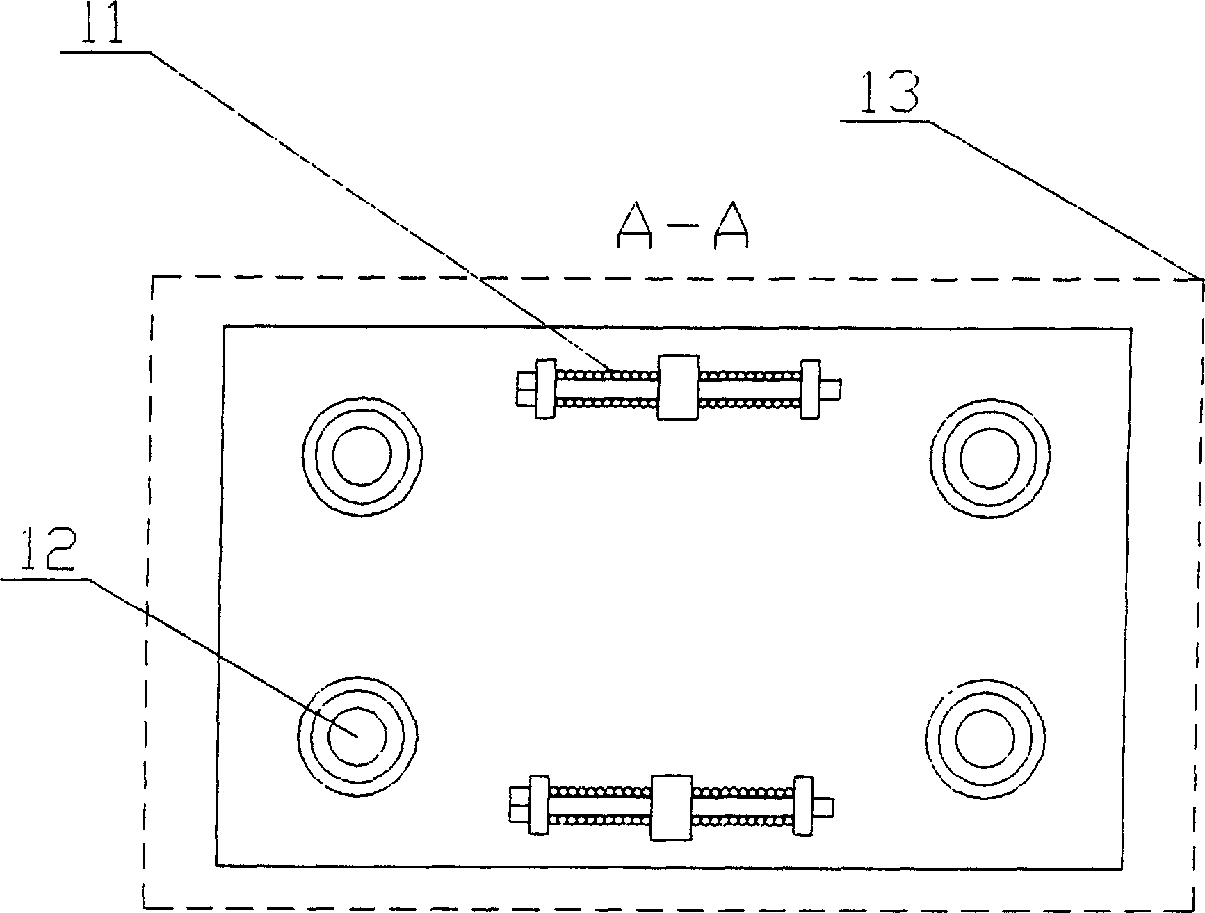
[0012] like figure 1 As shown, two horizontal adjustment springs 11 and four horizontal support balls 12 are arranged symmetrically between the bracket 13 and the movable support plate 10 . The horizontal adjustment spring 11 is formed by two springs connected in series through a connecting rod, and the connecting rod also passes through the spring connecting seats respectively positioned on the support 13 and the movable support plate 10 . The horizontal support ball 12 is fixed on the panel of the support 13 .

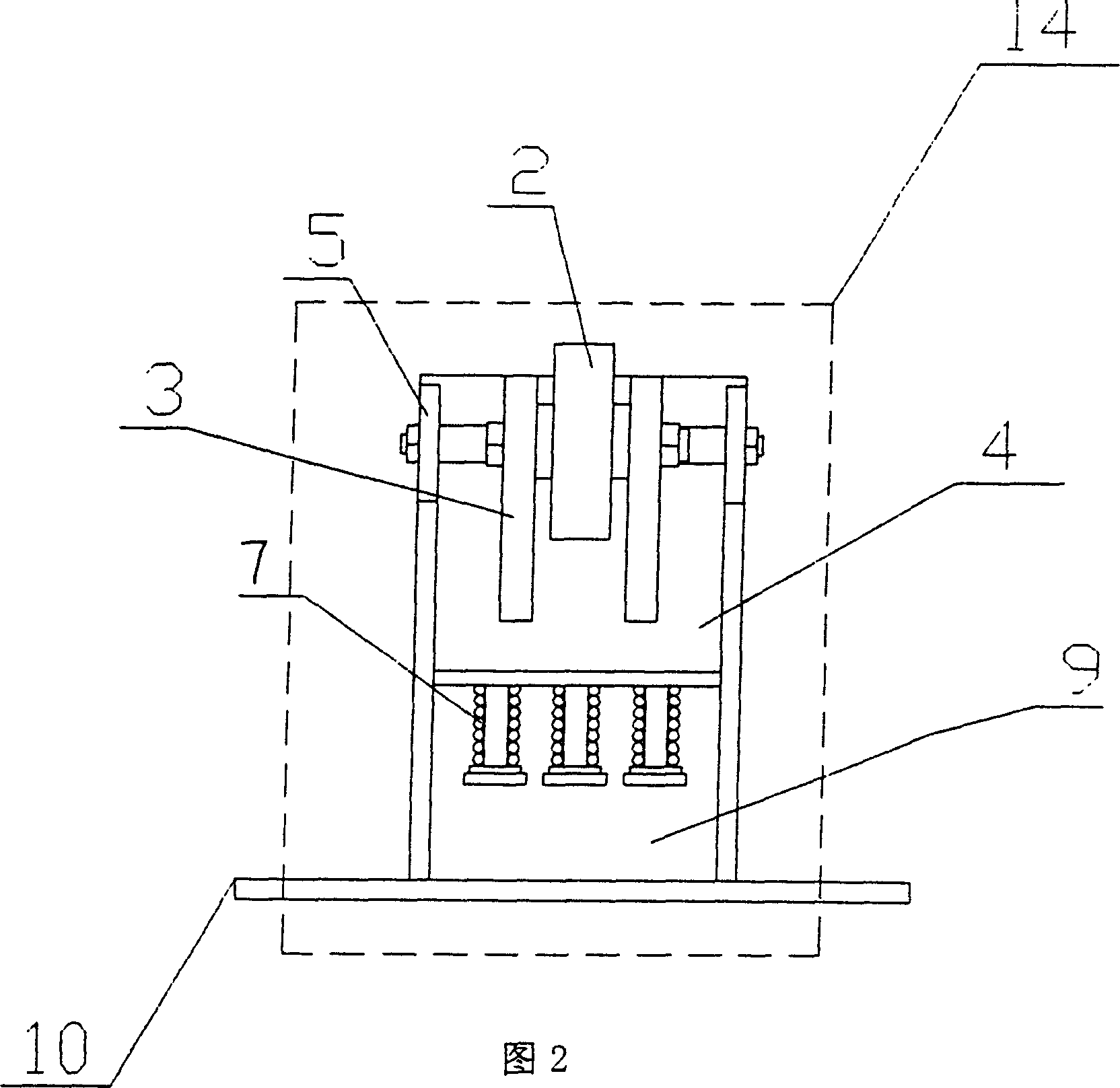
[0013] On the movable support plate, there are two left-right symmetrical clamping parts 14, the structure of which is shown in Figure 2, for the sake of clarity, the connecting and fixing plate 8 is omitted in the figure. The connection fixed plate 8 is vertically positioned at one side of the movable support plate 10, and the spring guide rod fixed plate 9 is arranged between the connected fixed plate 8 and the movable support plate 10, and the angle between the s...


PUM


Abstract

The present invention relates to a clamp apparatus for laser cutting petroleum pipe, said clamp apparatus comprises a support frame and a supporting component, between the support frame panel and movable supporting plate a horizontal regulating spring and symmetrically-arranged horizontal supporting rollers are set, on the movable supporting plate two left-right symmetrical holding components are set, and the connecting fixing plate on the holding component is perpendicular to one side of movable supporting plate, and between connecting fixing plate and movable supporting plate a spring guide bar fixing plate is set, its included angle alpha is greater than or equal to 30 deg. or less than or equal to 60 deg. Said invention can ensure continuity for cutting petroleum pipe.

Description

technical field [0001] The invention relates to a laser processing device, in particular to a fixture for laser cutting, especially suitable for laser cutting of oil pipes. Background technique [0002] In recent years, as laser processing has become more and more widely used in the industrial field, various laser processing equipment with different functions have come out one after another. Typical examples are laser cutting machines, laser welding machines and laser marking machines. This requires the design and production of a series of high-precision, high-performance fixtures to match it. [0003] Because the wall of the oil pipe is thicker, usually around 8-10mm, the pipeline is longer, usually between 8-12m. However, the processing stroke of the existing laser cutting machine is only about 3-5m, therefore, the method of segmental cutting is usually used for processing. Laser processing belongs to thermal processing. Sectional processing of such thickened and elonga...

Claims


Application Information

Patent Timeline
Patent Type & Authority Applications(China)
IPC IPC(8): B23K37/047
Inventor 廖炳华贺昌玉
Owner HUAZHONG UNIV OF SCI & TECH
Learn More