Wrapped steel wire

A steel wire rope, covering type technology, applied in the direction of transportation and packaging, transmission element or pulley rope or cable, coating, etc., can solve the problems of high price pulley, time-consuming, low position control accuracy and other problems

Active Publication Date: 2004-06-30
TOKYO ROPE MFG +1
View PDF0 Cites 16 Cited by
  • Summary
  • Abstract
  • Description
  • Claims
  • Application Information

AI Technical Summary

Problems solved by technology

According to this prior art, although metal contact between the core and the side strands is prevented, it is difficult to maintain an appropriate distance between the side strands
Therefore, the side strands rub against each other and tend to fray
In addition, the pulleys and the side strands usually slide relative to each other in metal contact, so the pulleys with low hardness are worn out, so there is a problem that the replacement of expensive pulleys is troublesome and time-consuming.
A...

Method used


Image

  • Wrapped steel wire
  • Wrapped steel wire
  • Wrapped steel wire

Examples


Embodiment Construction

[0041] Hereinafter, embodiments of the present invention will be described with reference to the drawings.

[0042] figure 1 - Figure 6 shows a first embodiment of a sheathed steel cord according to the invention.

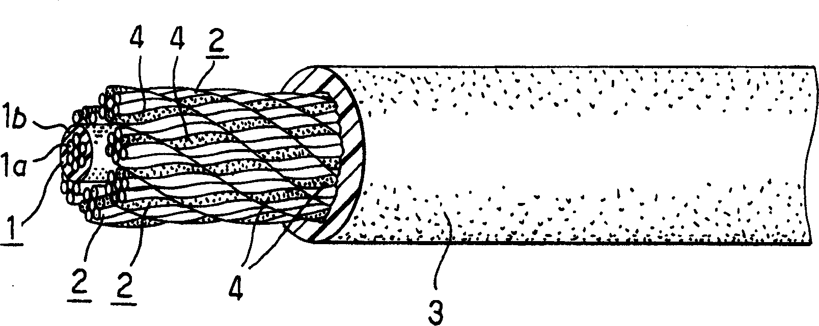
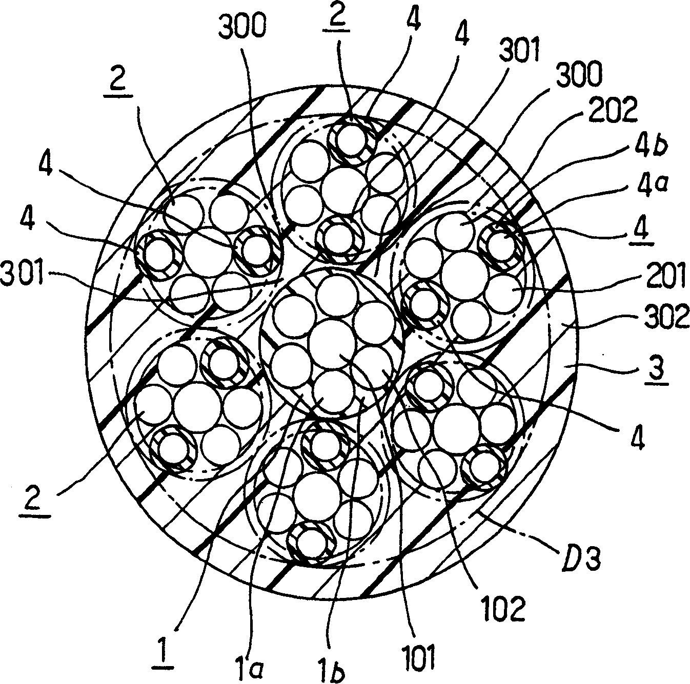
[0043] exist figure 1 , 2 In the figure, symbol 1 denotes a rope core, and a synthetic resin coating layer 1b is formed on the outer periphery of a rope core body 1a formed by twisting a single thin steel wire or a steel strand. Although the configuration of the core body 1a may be arbitrary, in this example, it has a 1×7 structure in which six side wires 102 are arranged around a center wire 101 and twisted together.

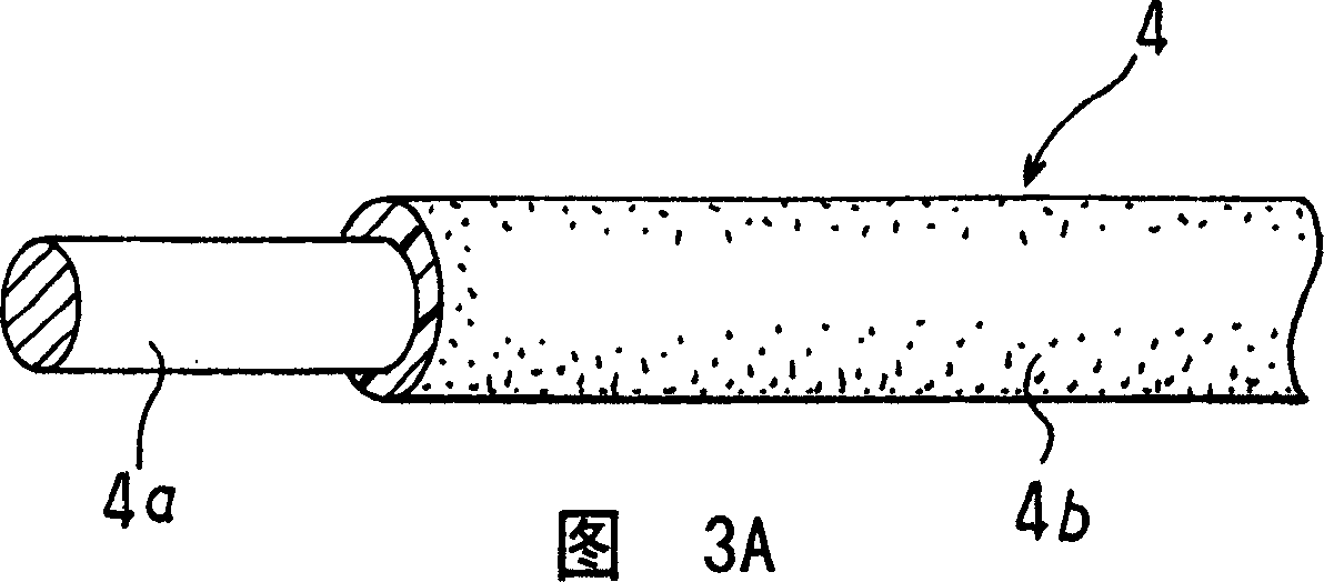
[0044]2 is a plurality of (six in the figure) side strands arranged around the core 1 and twisted. 3 is an outer covering layer (full covering) of synthetic resin applied to contain the side strands 2, which fills and blocks the gaps between the adjacent side strands 2 and 2, and the gap between each side strand 2 and the cord 1. gap.

[0045]...


PUM


Abstract

A steel cable rope well-suited for the application to an elevator or a cargo-handling machine, in which each of side strands is constructed by twisting ordinary linear members together with at least one resinous linear member that is larger in diameter than each of the ordinary linear members. Owing to the existence of the resinous linear member of the relatively larger diameter, gaps are respectively defined between the individual side stands and a core rope and between the respectively adjacent side strands, and a resin for outer layer coating is pressed and packed through the gaps, thereby to prevent wear ascribable to the touch between a core rope and the outer side strands, as well as wear ascribable to the touch between the adjacent outer side strands, and wear ascribable to the metal touch between a sheave and the outer side strands.

Description

technical field [0001] The invention relates to a sheathed steel wire rope suitable for use as a moving cable of an elevator, cargo handling machinery, etc. Background technique [0002] The moving ropes used in cargo handling machines represented by elevators and cranes are reeled up while being moved by pulleys. Therefore, it is known that there are severe conditions in which the entire rope is subjected to tension and bending. [0003] In the past, as this kind of dynamic rope, in accordance with JIS·G·3525 and 3546, etc., a rope constructed in such a way that a plurality of side strands are arranged on the outer peripheral surface of a rope core made of fibers or steel strands or steel wire ropes has been used. wires and twist them together. [0004] In this structure, however, a high surface pressure is generated on the core and the side strands, and since the rope is bent by a pulley or the like, friction of the core against the side strands occurs. Thus, when the ro...

Claims


Application Information

Patent Timeline
IPC IPC(8): D07B1/16B66B7/06D06B1/06D06B1/16D07B1/06
CPCD07B2201/2024D07B1/162D07B1/16D07B2201/2012D07B2401/208D07B1/165D07B2201/2023D07B2401/207D07B2501/2007D07B2201/2037D07B2201/2044D07B1/0673D07B1/068D07B2201/2036
Inventor 圆句幸作守谷敏之古川一平中村一朗大宫昭弘岩仓昭太
Owner TOKYO ROPE MFG
Why Eureka
Try Eureka