Diffraction image transmission method

An image and diffracted light technology, applied in the direction of diffraction grating, optics, instruments, etc., can solve the problems of not seeing, directly seeing the object image, rarely seeing the purpose of the grating to transmit the image, etc.

Inactive Publication Date: 2004-06-30
GUANGXI UNIV
View PDF0 Cites 4 Cited by
  • Summary
  • Abstract
  • Description
  • Claims
  • Application Information

AI Technical Summary

Problems solved by technology

This is because the object spectrum deviates from the original propagation direction after the object light wave passes through the grating. Although the object spectrum contains the image information of the object, these images are staggered and superimposed according to the color, so that the object image cannot be seen directly from it. image, so it is rare to see the use of rasters for image transfer purposes
Although gratings are also used in imaging systems, their function is to cooperate with traditional refractive optical elements to correct chromatic aberration rather than to achieve the purpose of gratings to transmit images.
[0003] On the other hand, if it is possible to extract the object image information in the object spectrum formed by the optical dispersion element, especially the object spectrum formed by grating diffraction, and re-form the original object image, this is of great practical significance, but in the prior art This technology has not yet been seen in

Method used


Image

  • Diffraction image transmission method
  • Diffraction image transmission method
  • Diffraction image transmission method

Examples


Embodiment Construction

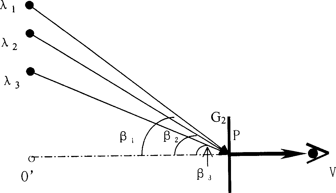
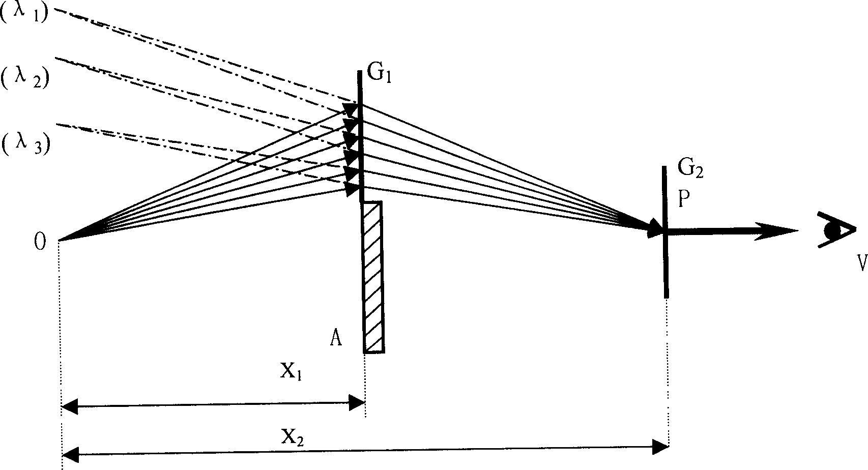
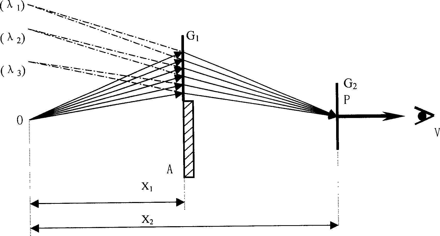
[0031] In each of the above-mentioned figures, only the optical path of this order of diffracted light beams that realize the converging spectral effect has been drawn, and other levels of light (including zero-order light) have not been drawn; and the optical path diagram is a top view of the actual optical path. Object O is a light-transmitting slit illuminated by an incandescent lamp (this object can be replaced with other bright objects). The present invention will be further described below in conjunction with the accompanying drawings, and the meanings of the mentioned parameters are consistent with the aforementioned grating imaging equation.

[0032] The converging spectral effect is the basis for the realization of the method of the present invention, figure 1 A schematic diagram of the confluence spectral effect. In the figure λ 1 , lambda 2 , lambda 3 is the spectrum formed by point objects arranged by color, in which light of different colors is incident on G a...


PUM


Abstract

The invention provides a method for transmitting image through diffraction, it mainly uses the grating confluence light spectrum effect, the grating (G2) is set into the proper position of object light spectrum generated by the (G1), the invention gets the beam which has confluences light spectrum effect in (G2) exit light, the beam synthesizes virtual image of original object from the virtual image which is divided by colors in object light spectrum, and observes the original object image.

Description

technical field [0001] The invention belongs to the field of optical imaging and relates to the transmission of object images by means of diffraction, in particular to the application of gratings. Background technique [0002] As a commonly used optical element, grating is widely used as a dispersion element because of its good dispersion effect, such as spectrometer, spectrograph, and monochromator as a spectroscopic element. In the prior art, gratings are generally not used for image transfer purposes. This is because the object spectrum deviates from the original propagation direction after the object light wave passes through the grating. Although the object spectrum contains the image information of the object, these images are staggered and superimposed according to the color, so that the object image cannot be seen directly from it. Because of this, it is rare to see the use of gratings for the purpose of transmitting images. Although ...

Claims


Application Information

Patent Timeline
Patent Type & Authority Applications(China)
IPC IPC(8): G02B5/18G02B27/42
Inventor 张卫平
Owner GUANGXI UNIV
Why Eureka
Try Eureka