

Electronic Component, transformer, inductor and method for manufacturing electronic components
A technology of electronic components and terminals, applied in transformer/inductor parts, inductance/transformer/magnet manufacturing, transformer/inductor coil/winding/connection, etc., can solve problems such as coil current value difference
- Summary
- Abstract
- Description
- Claims
- Application Information
AI Technical Summary
Problems solved by technology
Method used
Image

Examples
no. 1 example and
[0053] (First embodiment and configuration thereof)
[0054] Figure 5 to Figure 8 They are oblique view, front view, side view and plan view illustrating the structure of the transformer respectively. Hereinafter, for the sake of convenience, the winding 13 will be described as the primary winding and the winding 15 will be described as the secondary winding, but the relationship between the primary and secondary windings may be reversed. The figure shows a state where the magnetic core 12 is not inserted into the bobbin 11 , but the magnetic core 12 is inserted into the insertion opening 116 of the bobbin 11 unless it is an air-core transformer.
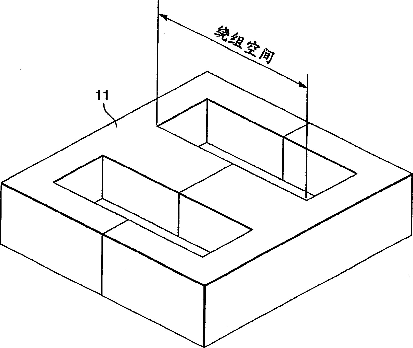
[0055] The bobbin 11 is a bobbin having a general-purpose reel core 111 using an electrically insulating material, and has flanges 112 , bases 113 , and core insertion openings 116 at both ends of the reel core 111 . Two terminal fixing portions 114 are arranged parallel to the reel core portion 111 on both sides of the reel core...
no. 2 example
[0074] Hereinafter, an electronic component according to a second embodiment of the present invention will be described. In the second embodiment, substantially the same configuration as that of the first embodiment is denoted by the same symbols, and detailed description thereof is omitted.
[0075] Figure 13 to Figure 15 A front view, a side view, and a plan view illustrating the construction of the transformer are shown, respectively.
[0076] The substrate 4 is a printed circuit board having terminals 34 for connecting terminals 34 of the transformer primary winding 13 . In addition, the terminal 34 may be formed as a copper foil pad of the substrate 4 in which a hole or a through hole into which the pin terminal 117 can be inserted is formed.
[0077] By winding the primary winding 13 on the bobbin core 111 and soldering the end portion of the winding to the terminal 34 in the same manner as in the first embodiment, the same effects as in the first embodiment can be ob...
no. 3 example
[0081] Hereinafter, an electronic component according to a third embodiment of the present invention will be described. In the third embodiment, components substantially the same as those in the first and second embodiments are denoted by the same symbols, and detailed description thereof is omitted.
[0082] Hereinafter, as a third embodiment, a transformer having a primary winding for a push-pull circuit will be described. Figure 18 This is a configuration example of a push-pull circuit. A transformer for a push-pull circuit has a set of primary windings connected in series, and the series connection point is taken out as a central tap of the primary winding.
[0083] Figure 19 It is a plan view illustrating the structure of a transformer. Unlike the second embodiment, the transformer of the third embodiment has two primary windings for a push-pull circuit, and the substrate 6 has terminals matching the configuration of the windings. also, Figure 19 I to VI shown cor...
PUM
| Property | Measurement | Unit |
|---|---|---|
| diameter | aaaaa | aaaaa |
| electrical resistance | aaaaa | aaaaa |
| electrical resistance | aaaaa | aaaaa |
Abstract
Description
Claims
Application Information