
Thermal fuse

A technology for thermal fuses and metal terminals, which is applied to electrical components, electric switches, circuits, etc., and can solve problems such as poor wettability and thermal fuses that cannot be blown quickly

Inactive Publication Date: 2004-06-30
PANASONIC CORP
View PDF0 Cites 7 Cited by
  • Summary
  • Abstract
  • Description
  • Claims
  • Application Information

AI Technical Summary

Problems solved by technology

At this time, the wettability of the metal terminal 1 and the first insulating film 2 to the soluble alloy 3 is poorer than that of the metal layers 5 and 6, so the movement of the soluble alloy 3 becomes slower during fusing, and as a result, the breaking of the soluble alloy 3 during fusing The opening becomes slow, and there is a problem that the thermal fuse cannot be blown quickly

Method used


Image

  • Thermal fuse
  • Thermal fuse
  • Thermal fuse

Examples


Embodiment approach 1

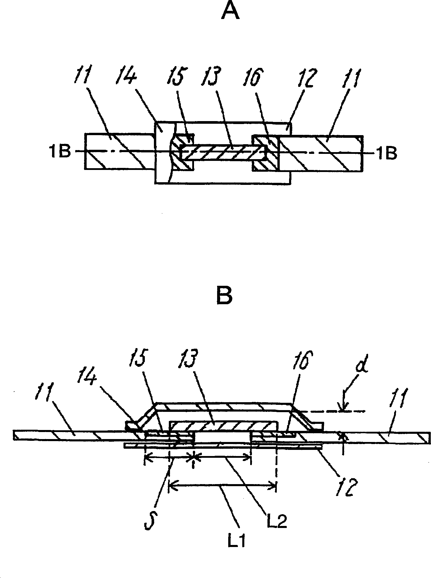
[0027] figure 1 A is a partially cut top view of the thermal fuse in Embodiment 1 of the present invention. figure 1 B is along figure 1 A is a cross-sectional view of the 1B-1B line of the thermal fuse.

[0028] The thermal fuse in Embodiment 1 includes: a first insulating film 12 on which the tip portions of the pair of metal terminals 11 are arranged, and is located above the first insulating film 12 and provided on the tip portions of the pair of metal terminals 11. The soluble alloy 13 in between is located above the soluble alloy 13 and is fixed to the second insulating film 14 on the first film 12 and the metal terminal 11. Metal layers 15 and 16 that are more wettable to the soluble alloy 13 than the metal terminals 11 and the first insulating film 12 and connected to the soluble alloy 13 are provided on the tip portions of the pair of metal terminals 11 .

[0029] Taking the area of ​​the metal layers 15 and 16 as S, the length and volume of the soluble alloy 13...

Embodiment approach 2

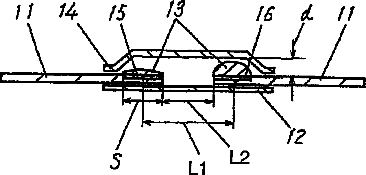
[0057] Figure 4 A is a partially cut top view of the thermal fuse in Embodiment 2 of the present invention. Figure 4 B is along Figure 4 A shows a cross-sectional view of line 4B-4B of the thermal fuse.

[0058] Those having the same configuration as those in Embodiment 1 are denoted by the same symbols and their descriptions are omitted.

[0059] exist Figure 4 In A, the difference from Embodiment 1 is that the tip portions of the pair of metal terminals 11 are formed so as to protrude from the lower surface to the upper surface of the first insulating film 12, and at least a part of the protruding portion is provided with a metal with good wettability. Layers 15, 16.

[0060] In the thermal fuse according to the second embodiment, the metal layers 15 and 16 having better wettability than the metal terminal 11 and the first insulating film 12 are provided on part or all of the protruding portion of the metal terminal 11 . Taking the area of ​​the metal layers 15 and ...


PUM

PropertyMeasurementUnit
Lengthaaaaaaaaaa
Thicknessaaaaaaaaaa
Young's modulusaaaaaaaaaa

Abstract

A thermal fuse having a quick melting property is provided. In the thermal fuse, metal layers 15, 16 connected to a fusible alloy 13 are provided at respective leading ends of a pair of metal terminals 11. The metal layers 15, 16 have larger wettability to a fusible alloy 13 than wettability of metal terminals 11 and first insulating film 12. The area (S) of the metal layers 15, 16, the length (L1) and the volume (V) of the fusible alloy 13, the distance (L2) between the leading ends of the metal terminals 11, and the distance (d) from the bottom face of the second insulating film 14 to the top face of the metal layers 15,16 satisfy the relation of Sd>V(L1+L2) / 2L1.

Description

technical field [0001] The present invention relates to a thermal fuse. Background technique [0002] In recent years, with the miniaturization of electronic equipment, for example, the thickness of an assembled battery of a conventional mobile phone is 5 mm to 6 mm, but a small and thin assembled battery with a thickness of 2.5 mm to 4 mm is required. Since the above-mentioned electronic equipment is miniaturized, its heat capacity is reduced, and the temperature rise rate when generating heat tends to be accelerated. Therefore, there is a demand for a thermal fuse with quick-acting properties for its protection in the market. [0003] Figure 5 A is the top view of the existing thermal fuse partially cut, Figure 5 B is along Figure 5 A cross-sectional view of line 5B-5B. [0004] like Figure 5 A and Figure 5 As shown in B, the existing thermal fuse has: a first insulating film 2 on which the top ends of a pair of metal terminals 1 are arranged, located above the firs...

Claims


Application Information

Patent Timeline
IPC IPC(8): H01H37/76
CPCH01H2037/768H01H37/761
Inventor 仙田谦治河野笃司
Owner PANASONIC CORP
Learn More