Image processor, image processing method and programm

An image processing device and image processing technology, applied in image communication, optics, instruments, etc., can solve problems such as error-prone, unnoticed film degradation, and density reduction

Inactive Publication Date: 2004-07-07
KONICA MINOLTA INC
View PDF2 Cites 5 Cited by
  • Summary
  • Abstract
  • Description
  • Claims
  • Application Information

AI Technical Summary

Problems solved by technology

[0017] However, even in the device described in the above-mentioned Patent Document 2, no attention is paid to the effect of film degradation over time, and since this effect still exists, it is difficult to stabilize the density.
[0018] However, each device of the exposure system and thermal development system includes a factor of variation, and the film also changes with time, so there is a problem that the setting of the amount of change in the characteristics and the density value for comparison is prone to errors. Therefore, if the aforementioned characteristics The setting of the change amount and the density value for comparison are different, and even if the processing system reproduces the density as set, the density decreases and the density increases as a result.

Method used


Image

  • Image processor, image processing method and programm
  • Image processor, image processing method and programm
  • Image processor, image processing method and programm

Examples


Embodiment 1

[0081] Figure 4 It is a block diagram illustrating the functions of the first embodiment of the image processing apparatus for implementing the image processing method of the present invention. Figure 5 is for illustration Figure 4 A flow chart of processing performed by the image processing device is shown.

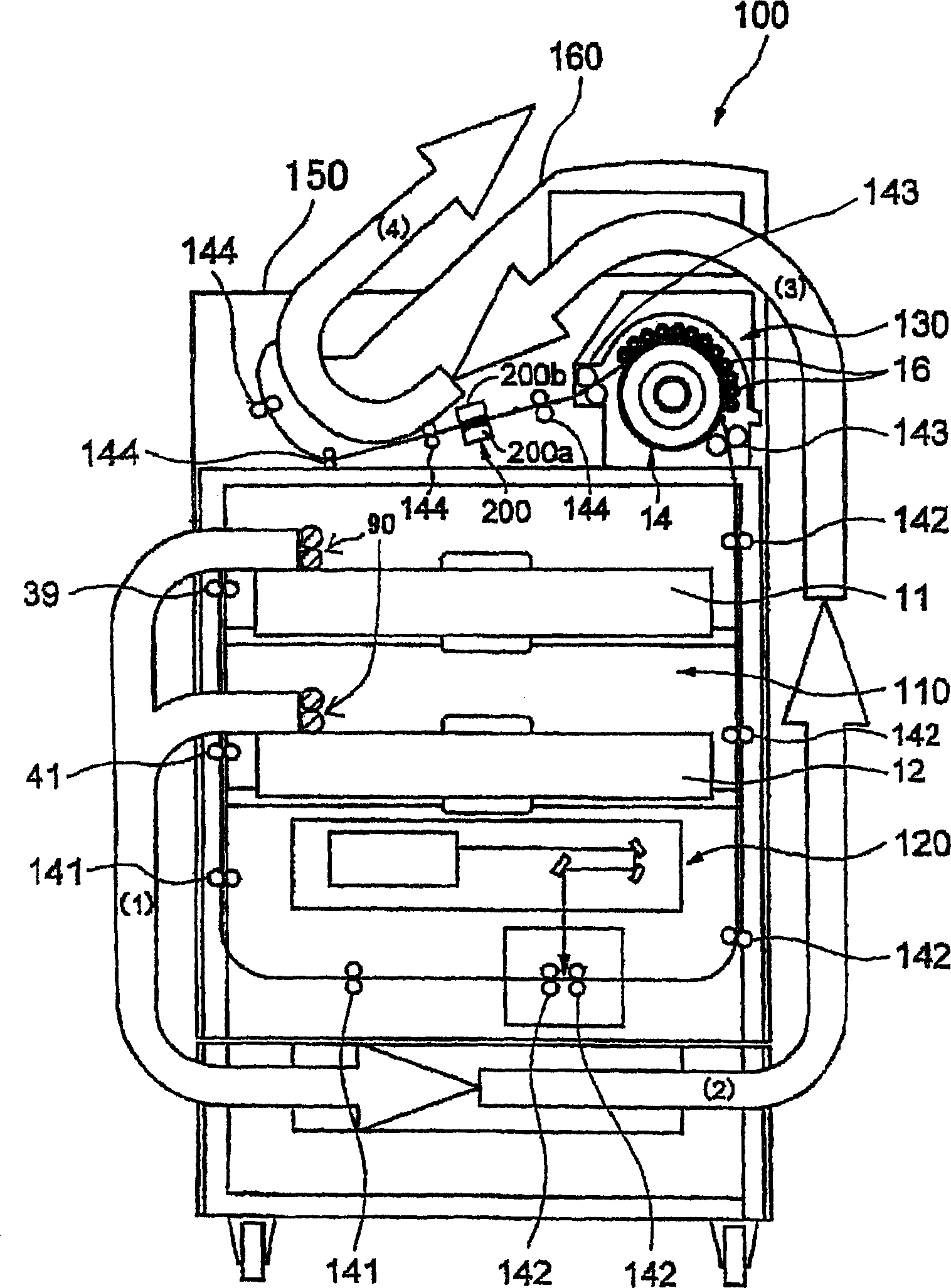
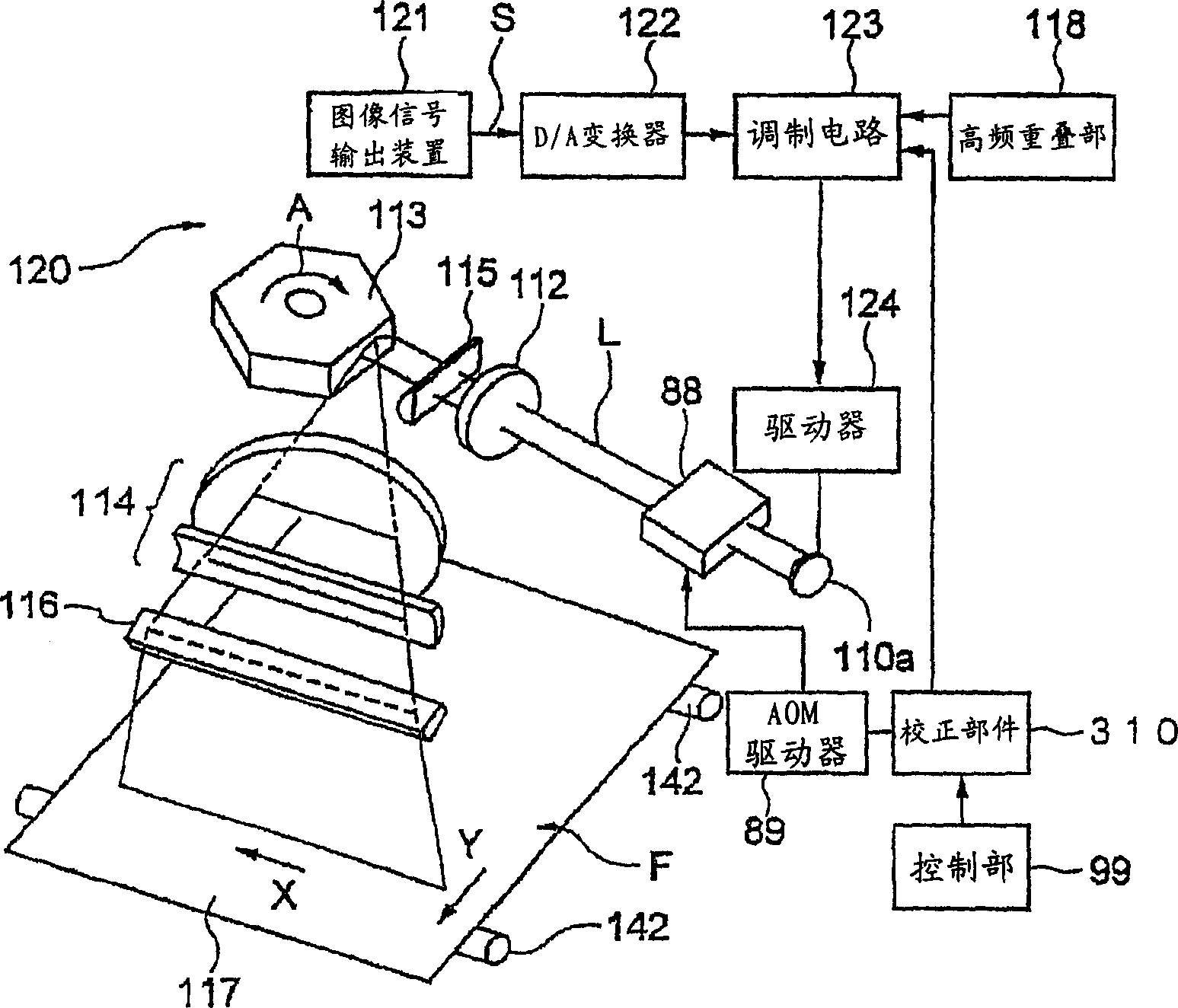
[0082] like Figure 4 As shown, the image processing apparatus of this embodiment includes: an exposure unit 120 for implementing an exposure process, a developing unit 130 for implementing a developing process, a testing unit 200 for implementing a testing process, and a calibration unit for implementing a calibration process 300. A storage component 400 for implementing a storage process, a differential calculation component 500 for implementing a differential calculation process, and a correction component 600 for implementing a correction process.

[0083] like Figure 5 As shown, exposure and development are performed in the exposure unit 120 and the developm...

Embodiment 2

[0095] Figure 11 It is a flowchart for explaining the processing performed by the image processing apparatus of the second embodiment. And the second embodiment can be used with Figure 4 Same block diagram description. Unlike the first embodiment, which corrects the correction table according to the characteristic change pattern of the exposure unit 120 and / or the developing unit 130, this embodiment performs correction according to the temporal characteristic pattern of the film.

[0096] like Figure 11 As shown, exposure and development are performed in the exposure unit 120 and the development unit 130 (S11). In this case, the image data for exposure and development is image data for testing. The test image data includes various image signals as test patterns.

[0097] The density of the exposed / developed film is tested by a test unit (S12).

[0098] Based on the test image data and the results of the test in S12, a correction table for specifying the image density...

Embodiment 3

[0107] Figure 13 It is a block diagram illustrating the functions of the third embodiment of the image processing apparatus for implementing the image processing method of the present invention. Figure 14 is for illustration Figure 13 A flow chart of processing performed by the image processing device is shown.

[0108] This embodiment includes both the modification of the correction table according to the characteristic change pattern of the exposure unit 120 and / or the developing unit 130 in the first embodiment and the modification of the correction table according to the temporal characteristic pattern of the film in the second embodiment.

[0109] The image processing device of this embodiment is such as Figure 13 As shown, it includes an exposure unit 120 for implementing an exposure process, a developing unit 130 for implementing a developing process, a test unit 200 for implementing a test process, a calibration unit 300 for implementing a calibration process, an...


PUM


Abstract

An image processing apparatus, comprising: an exposing device for exposing an image forming material so as to form a latent image on the image forming material based on image data; a developing device for developing and visualizing the latent image on the exposed image forming material so as to form an image; a measuring device for measuring the image density of the image on the developed image forming material; a calibrating device for forming a table to define a relation between an image signal and image density on the basis of plural different test image data and measured-image densities thereof; a storing device for storing a characteristic change model indicating a characteristic change of at least one of the exposing device and the developing device with time; a difference calculating device to calculate a density difference on the basis of the characteristic change model between the time of forming the table and the time of forming an image based on image signal of diagnostic image data; and a correcting device for correcting the table on the basis of the density difference calculated by the difference calculating device.

Description

technical field [0001] The present invention relates to an image processing device, an image processing method, and a program, and more particularly, to an image processing device capable of finishing a film at an appropriate density during image formation and always maintaining a stable density and outputting the image processing device. , image processing method and program. Background technique [0002] In medical laser imaging devices (image processing devices), in order to express diagnostic images in gradation, there is a strong demand for a basic function of maintaining stable output of gradation. [0003] In addition, in medical laser imaging devices, in order to control the image forming part so that the digital and video signals (specified density signals) sent from diagnostic devices and imaging devices have a constant density on the film, a so-called calibration function is provided. . [0004] However, after the calibration is performed, although a certain con...

Claims


Application Information

Patent Timeline
Patent Type & Authority Applications(China)
IPC IPC(8): B41J2/47G03C5/02G03D13/00H04N1/40H04N1/407H04N1/60
CPCH04N1/4076H04N1/40006
Inventor 小野阳一下地雅也
Owner KONICA MINOLTA INC
Why Eureka
Try Eureka