Current feedback circuit

A current feedback, circuit technology, applied in the field of output current voltage conversion unit

Inactive Publication Date: 2004-07-14
MITSUMI ELECTRIC CO LTD
View PDF1 Cites 6 Cited by
  • Summary
  • Abstract
  • Description
  • Claims
  • Application Information

AI Technical Summary

Problems solved by technology

Therefore, there is a problem that a resistor that receives the output voltage from the output current-voltage conversion unit is required, and the resistance value of this resistor must be appropriately designed in this transfer function

Method used


Image

  • Current feedback circuit
  • Current feedback circuit
  • Current feedback circuit

Examples


Embodiment Construction

[0023] The embodiments of the present invention will be described below with reference to the drawings.

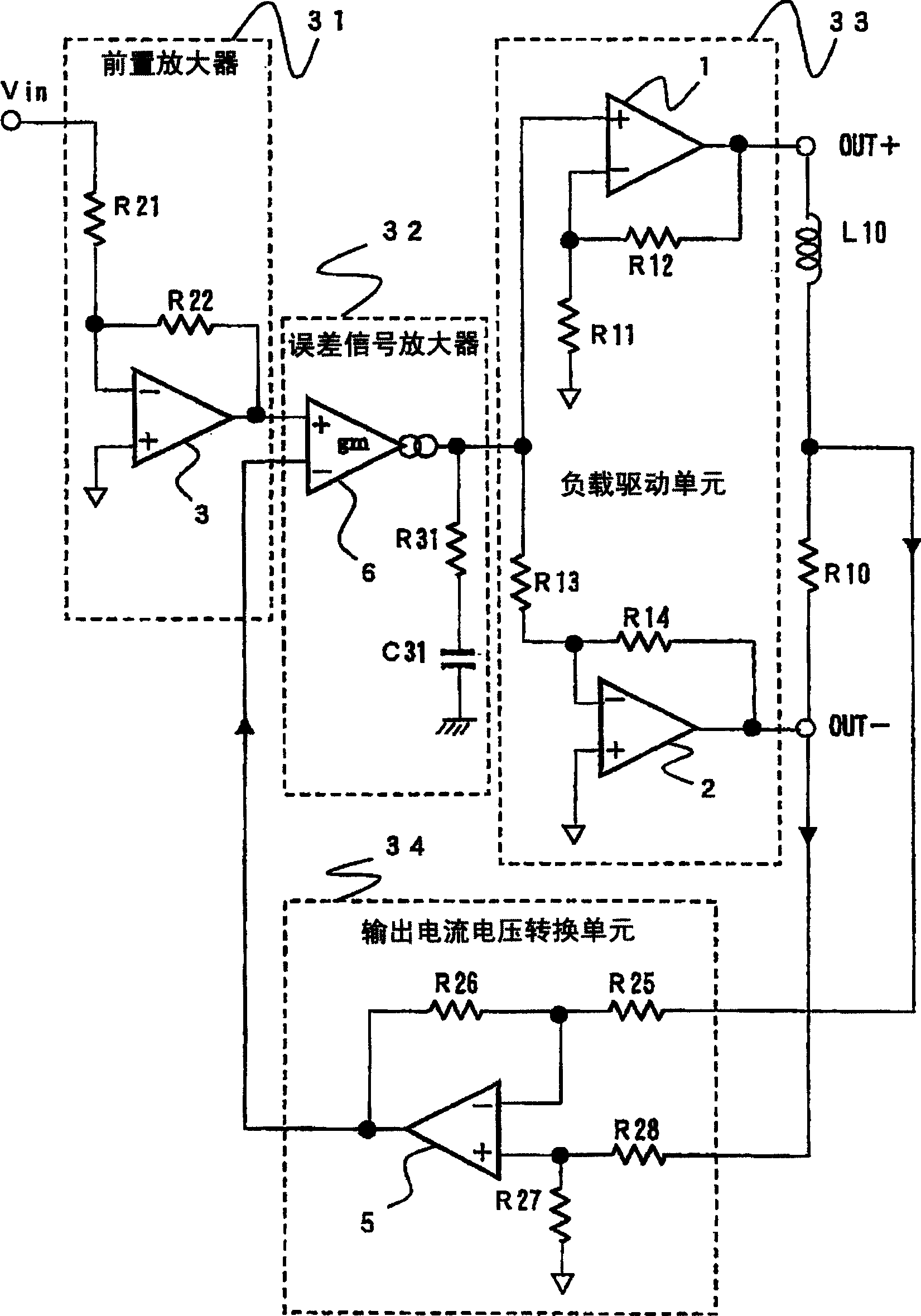
[0024] image 3 It is a block diagram showing a circuit of an embodiment of the present invention.

[0025] image 3 The entire circuit shown is composed of a preamplifier 31, an error signal amplifier 32, a load driving unit 33, an output current-voltage conversion unit 34, a load L10 and a load resistance R10. The current feedback circuit that is the object of the present invention is related to the following: an output current-voltage conversion unit 34 that extracts the output current of the entire circuit and obtains a feedback signal converted into a voltage; and controls the input from the input terminal Vin of the entire circuit by the feedback signal Signal error signal amplifier 32.

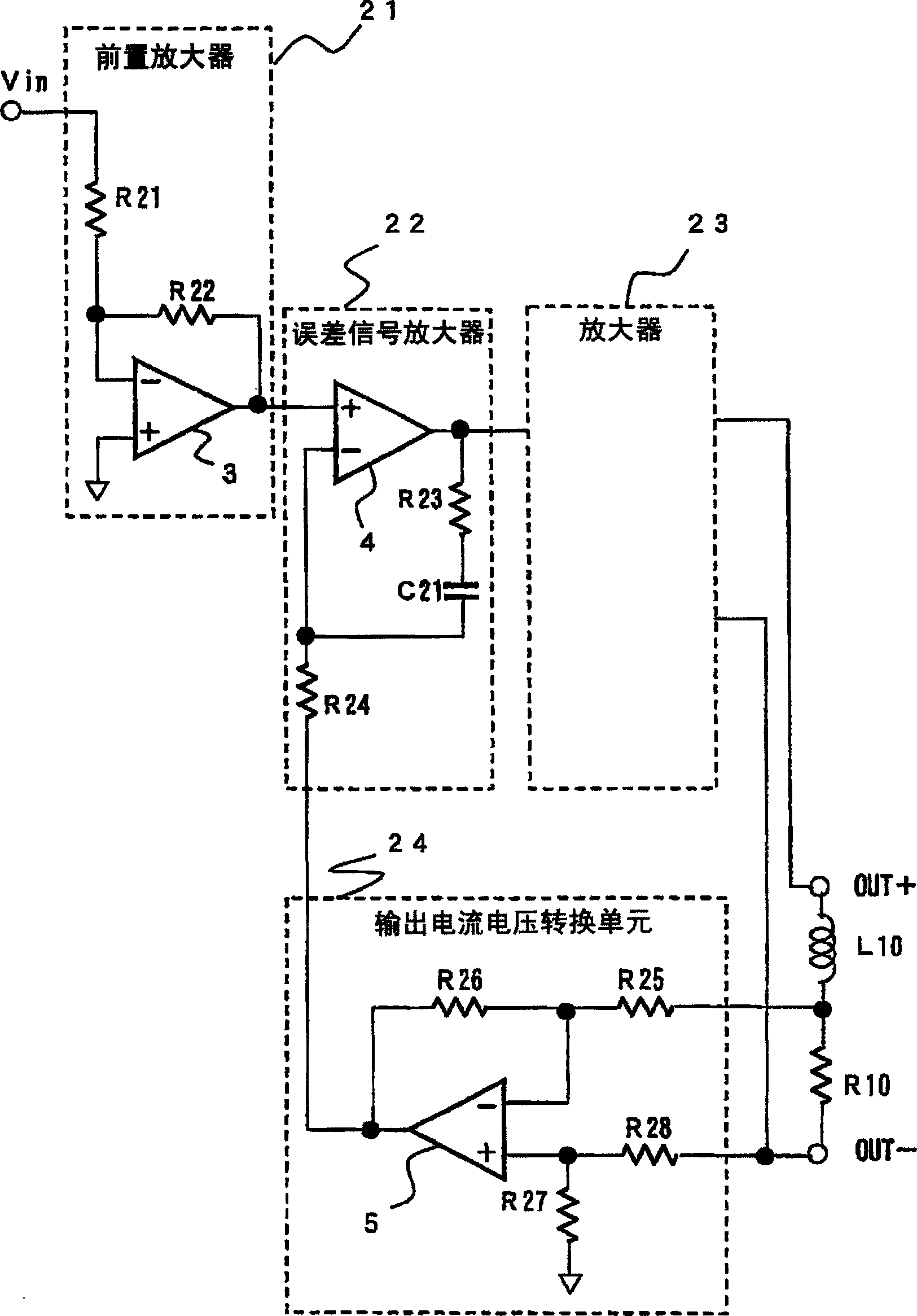
[0026] The feature of the present invention is the error signal amplifier 32. In addition, in image 3 In, and figure 2 Those with the same name, except the error signal amplifier 3, th...


PUM


Abstract

To satisfy a specified frequency band over a wide range by regulating the phase characteristics of an input signal using an operational amplifier arranged differently from a feedback amplifier at an error amplifier section, and to prevent oscillation while having a sufficient phase margin in the frequency characteristics of an open loop. An error amplifier section 32 for amplifying the input signal of the entire circuit depending on a feedback signal from an output current voltage converting section 34 for voltage converting the output current of the entire circuit is provided with a voltage control/current output type operational amplifier 6 having a transfer conductance gm and outputs a current of an amplified input signal. The operational amplifier 6 has a constant current source and the characteristics of a differential amplification circuit based on the transfer conductance gm. Consequently, a phase regulation circuit corresponding to the operational amplifier 6 comprises a resistor R31 and a capacitor C31 being connected in series between the output terminal of the operational amplifier 6 and the earth potential.

Description

Technical field [0001] The present invention relates to a current feedback circuit, which includes: inserting a load resistor on the output side of an amplifier circuit that outputs a voltage corresponding to an input signal, extracting the obtained current as a feedback current, and converting the feedback current into a voltage output current voltage Conversion unit; input the output signal of the output current-voltage conversion unit and the input signal, amplify the input signal according to the output signal and output to the error signal amplifier of the load drive unit, especially the error signal amplifier can be used in the error signal amplifier other than the feedback amplifier Structure of the current feedback circuit of the operational amplifier. Background technique [0002] In the past, in this kind of current feedback circuit, the output side of a balanced transformer (BTL) circuit in which a load is connected between the output ends of two circuits that form opp...

Claims


Application Information

Patent Timeline
Patent Type & Authority Applications(China)
IPC IPC(8): H03F1/34H03F3/34H03F3/45H03F3/68
CPCH03F3/45475H03F3/68
Inventor 山里启介大原智光铃木大介
Owner MITSUMI ELECTRIC CO LTD
Why Eureka
Try Eureka