Pin hole detector

A detector and pinhole technology, applied in the field of pinhole detectors

Inactive Publication Date: 2004-07-14
HAMAMATSU PHOTONICS KK
View PDF1 Cites 4 Cited by
  • Summary
  • Abstract
  • Description
  • Claims
  • Application Information

AI Technical Summary

Problems solved by technology

That is to say, no matter what kind...

Method used


Image

  • Pin hole detector
  • Pin hole detector
  • Pin hole detector

Examples


Embodiment Construction

[0022] A pinhole detector according to an embodiment will be described below. The same symbols are used for the same components, and repeated explanations are omitted.

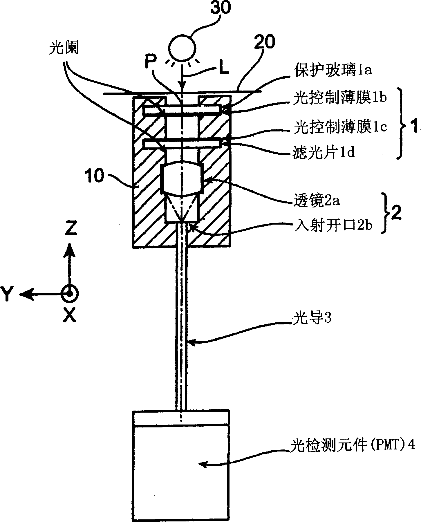
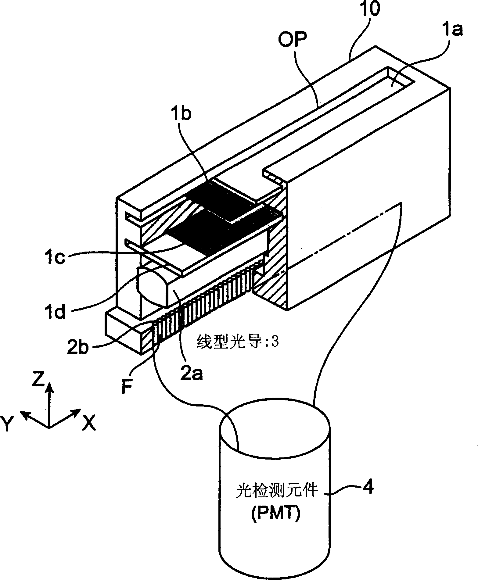
[0023] figure 1 It is a longitudinal sectional view of the pinhole detector of the embodiment, figure 2 is a perspective view of the pinhole detector partially cut away.

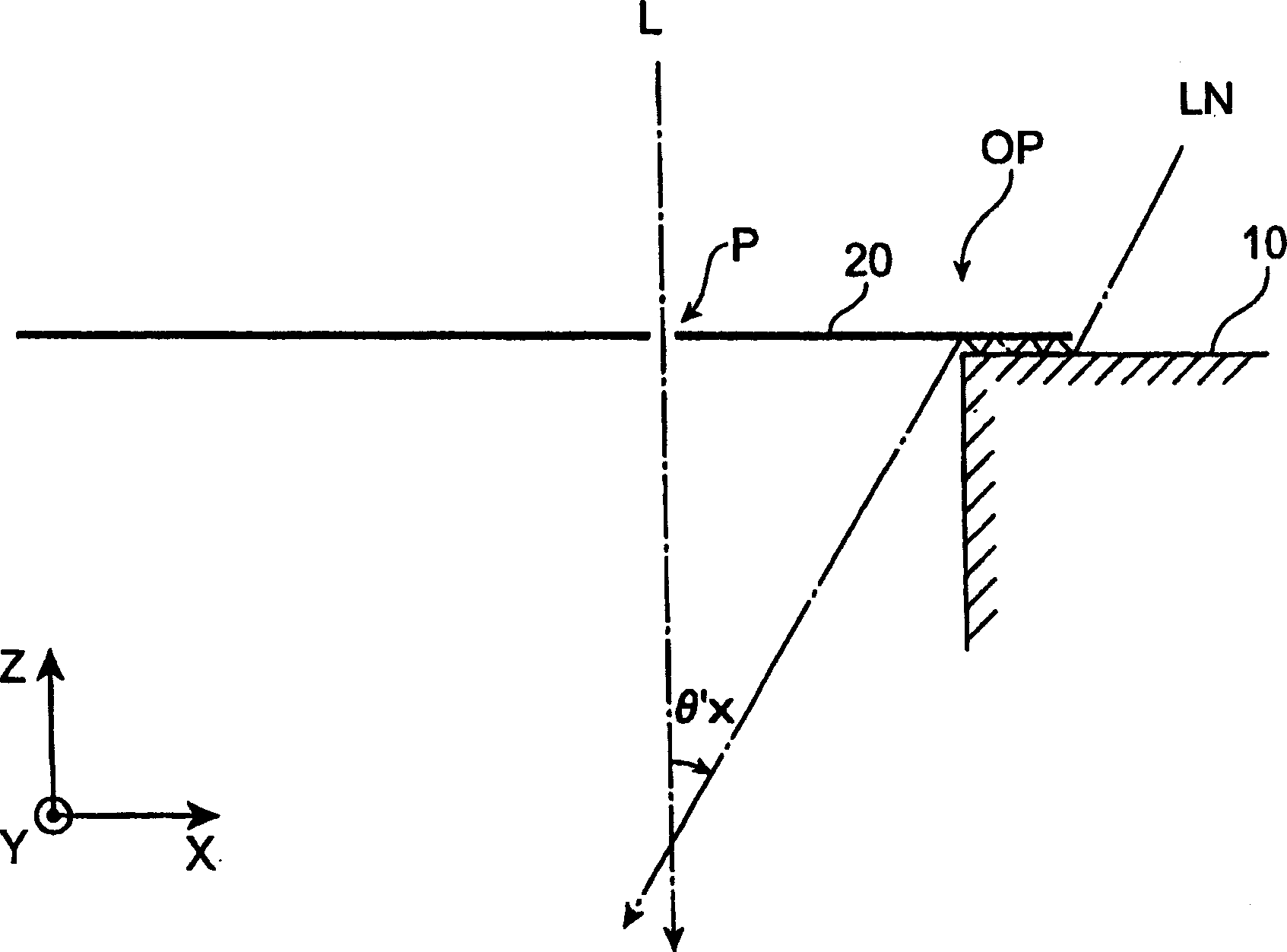
[0024] The pinhole detector has a dark box 10 in which an opening is formed on one side (upper surface). The object to be measured 20 is disposed on the opening end surface of the dark box 10 so as to cover the opening OP, and the light source 30 is located on the object to be measured 20 .

[0025] In addition, the object 20 to be measured in this example adopts a rolled aluminum film, and the film is moved along the Y-axis direction.

[0026] The light L emitted from the light source 30 passes through the pinhole P formed on the object 20 to be measured, the first optical means 1 arranged inside the opening end of the dark box 10, and...


PUM


Abstract

A pin hole detector, wherein light (L) passed through a pin hole (P) along a Z-axis direction is bound to a light detection element (4) but, since the advancing direction of noise light other than the light passed through the pin hole (P) is tilted relative to the Z-axis, the binding of the noise light to the light detection element (4) is limited by first and second optical means (1, 2) limiting an incidence angle, whereby the detector does not necessarily need a closed space when detecting, and can easily detect the pin hole (P).

Description

technical field [0001] The present invention relates to pinhole detectors. Background technique [0002] Conventionally, detection of pinholes formed in thin films such as metals and resins has been performed. In order to detect the pinholes formed by the rubber-like film, the film can be used to form a part of a closed container, and the container can be filled with liquid to detect whether the liquid leaks from the container. On the other hand, in order to detect pinholes formed in the metal thin film, the thin film can be used to constitute a part of a sealed dark box, and whether or not light passes through the pinholes can be detected inside the dark box. That is to say, no matter what kind of detection, an occluded space is required. Contents of the invention [0003] But detection with occluded space is not very easy, and there are many cases where detection with occluded space cannot be performed. F...

Claims


Application Information

Patent Timeline
IPC IPC(8): G01N21/894G02B5/00
CPCG01N21/894
Inventor 小池隆
Owner HAMAMATSU PHOTONICS KK
Why Eureka
Try Eureka