Antenna and its mfg. method

A technology for antennas and antenna units, applied to antennas, antenna parts, and other household appliances, can solve the problem of uneven thickness of resin coating

Inactive Publication Date: 2004-07-21
YOKOWO CO LTD
View PDF1 Cites 0 Cited by
  • Summary
  • Abstract
  • Description
  • Claims
  • Application Information

AI Technical Summary

Problems solved by technology

Ultimately, the resin molded part does not hold the correct position within the mold, resulting in severe unevenness in the thickness of the resin coating

Method used


Image

  • Antenna and its mfg. method
  • Antenna and its mfg. method
  • Antenna and its mfg. method

Examples


Embodiment Construction

[0035] Preferred embodiments of the present invention will be described in detail below with reference to the accompanying drawings.

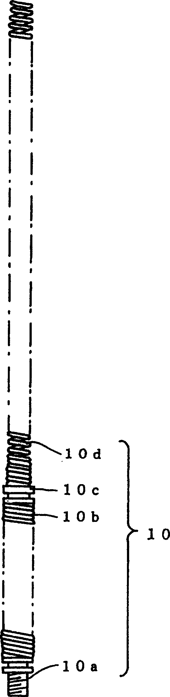
[0036] like figure 1 As shown, an antenna unit 10 includes: a fastening screw 10a on the bottom end; a spring portion 10b of a solid coil located above the fastening screw 10a; a connecting fitting 10c; Helical coil element 10d on top of portion 10b. The fastening screw 10a, the spring portion 10b, the connection fitting 10c and the helical coil element 10d are integrally connected electrically to operate as an antenna.

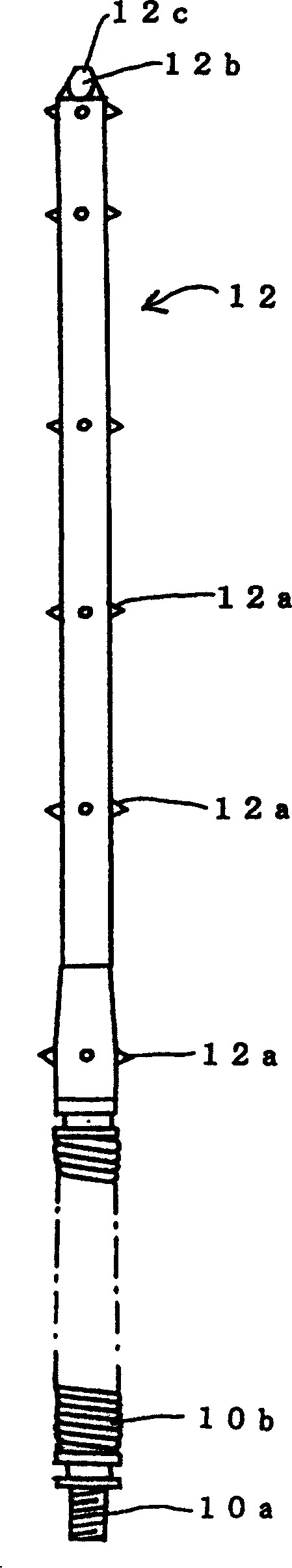
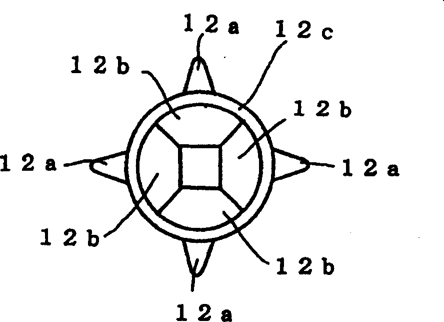
[0037] Portions of the antenna unit 10 corresponding to the connection fitting 10c and the helical coil element 10d are inserted into an unshown mold to form a resin molded part. The outer circumference of the helical coil element 10d just comes into contact with the inner surface of the mold to be placed in a predetermined position. Insulating resin is injected into the mold so that a resin molded part 12 is integrally mol...


PUM


Abstract

An antenna element is placed in a first mold for molding a first resin member including a plurality of protrusions, formed on an outer peripheral face of the first resin member and arranged with a fixed interval relative to a circumferential direction of the first resin member, and a tip end portion, having a cross sectional shape in which projected portions are arranged with a fixed interval relative to the circumferential direction of the first resin member. Insulating resin is injected into the first mold to form the first resin member. The first resin member is placed in a second mold such that the protrusions are brought into contact with an inner face of the second mold. Insulating resin is injected into the second mold from a gate confronting the tip end portion of the first resin member, to form a second resin member coated on the first resin member.

Description

technical field [0001] The present invention relates to an antenna using an antenna element composed of a helical coil or the like, and a method of manufacturing the antenna. Background technique [0002] An antenna configured using an antenna unit composed of a helical coil or the like is generally used for automobiles or mobile phones. In this antenna, a change in the pitch of a helical coil or the like causes a change in its antenna characteristics. In order to maintain a constant antenna characteristic, the shape of the helical coil must be fixed so as to avoid variations in its pitch or the like. [0003] Japanese Patent Publication No. 2000-252733A discloses that an antenna unit composed of a helical coil is first inserted into a mold, and the outer circumference of the antenna unit is just in contact with the inner surface of the mold so that it is placed in a predetermined position within. Next, insulating resin is injected into the m...

Claims


Application Information

Patent Timeline
Patent Type & Authority Applications(China)
IPC IPC(8): B29C45/14B29C45/16H01P11/00H01Q1/36H01Q1/40
CPCB29L2031/3456H01Q1/362H01Q1/40B29C45/16B29C45/14065B29C2045/1681
Inventor 大野贞夫笠神茂伸
Owner YOKOWO CO LTD
Why Eureka
Try Eureka