Wirewound device

A winding device and wire technology, applied in the manufacture of magnetic deflection devices, electrode devices and related components, coil manufacturing, etc., can solve the problem of increased friction between the wire and nozzle, increased wire tension, and inconsistent shape and characteristics of the deflection coil. Stability and other issues to achieve the effect of improving accuracy

Inactive Publication Date: 2004-07-28
NITTOKU ENG CO LTD
View PDF3 Cites 2 Cited by
  • Summary
  • Abstract
  • Description
  • Claims
  • Application Information

AI Technical Summary

Problems solved by technology

[0007] However, in the existing winding device, during the winding operation, the wire drawing end of the nozzle is fixed at a certain angle, so for example, when the nozzle is lowered with the wire drawing end facing down, the wire needs to be drawn from the wire. The pull-out end is pulled out with a roughly 180-degree bend, which will increase the friction between the wire and the nozzle, so the tension on the wire will also increase
In addition, in the existing winding device, the tension applied to the wire also changes depending on the winding position, which also causes the shape and characteristics of the deflection yoke to be unstable

Method used


Image

  • Wirewound device
  • Wirewound device
  • Wirewound device

Examples


Embodiment Construction

[0034] Embodiments of the present invention will be described below with reference to the drawings.

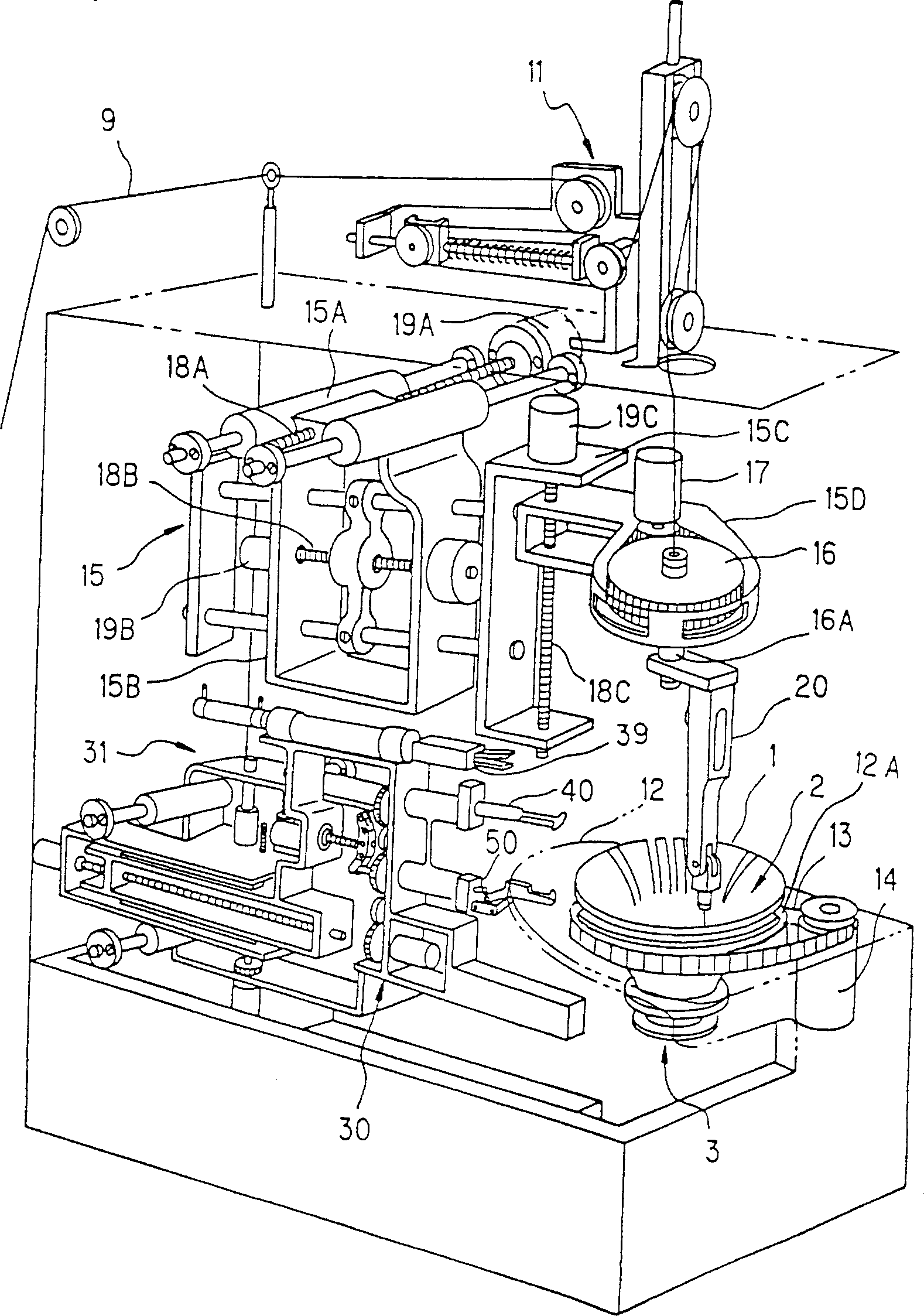
[0035] figure 1 The overall structure of the deflection yoke winding device of the present invention is shown.

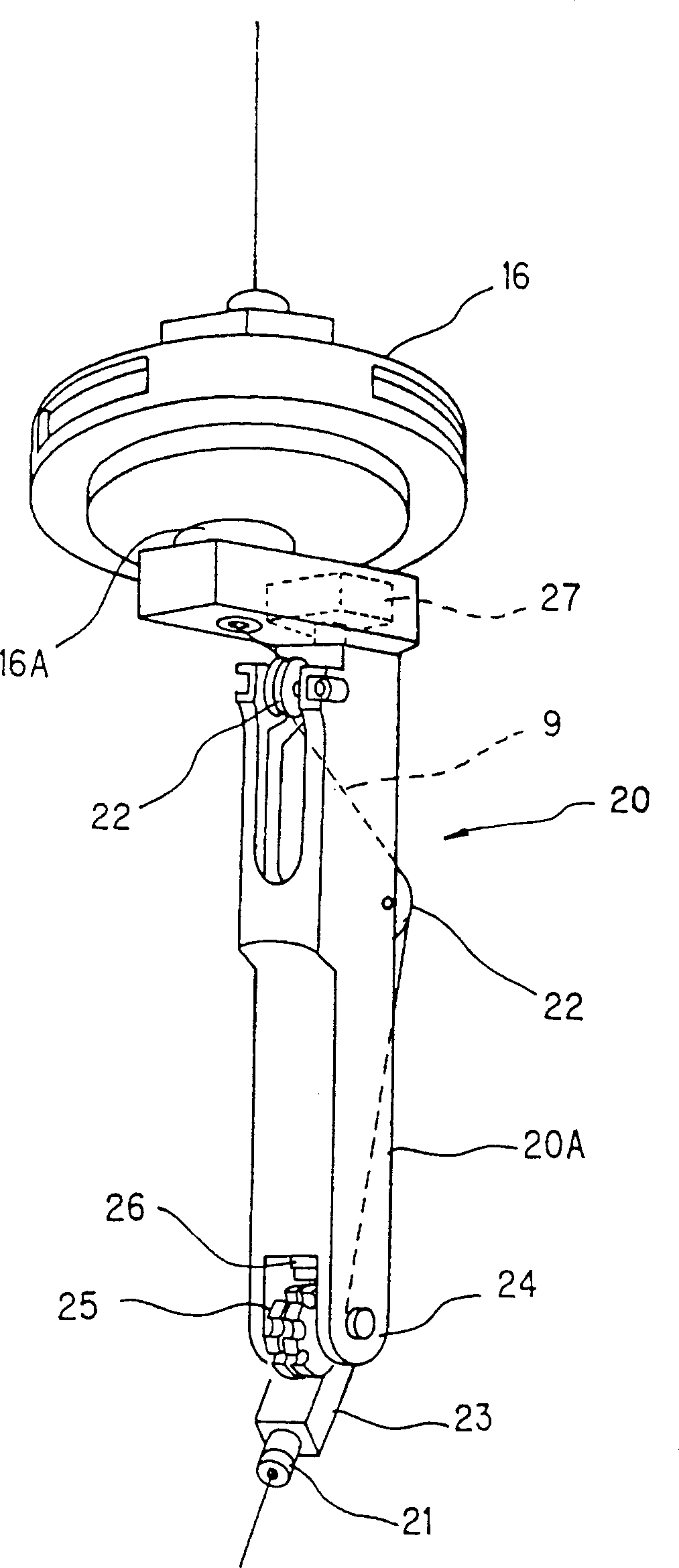
[0036] The wire 9 is drawn out from a bobbin not shown in the figure, and after a predetermined tension is applied to it by a tension device 11, it is guided to a wire supply device 20 below the tension device 11. The wire supply device 20 is disposed above the table-shaped bobbin support part 12 provided on the winding device casing, and the wire 9 extracted from the nozzle 21 at the front end of the wire supply device 20 is guided to the coil frame (deflection coil frame) 1. , On the rotary member 12A of above-mentioned bobbin supporting part 12, have a hole, bobbin 1 fits in this hole from small-diameter opening part 3, and large-diameter opening part 2 is supported by the rotary member 12A of bobbin supporting part 12. Wherein, the structure of the bobbin 1 i...


PUM


Abstract

To improve accuracy of the shape and characteristics of a coil (a deflection yoke) by accurately guide a wire to the specified winding position of a spool. A nozzle supporting part for supporting a nozzle is rotatably pin-connected to the tip of a wire supplying device capable of being freely moved in the three dimensional direction by a moving device, an engaging member to be freely turned in the normal state and to be engaged with a gear provided on the base end of the nozzle supporting part is provided, and the turning angle of the nozzle supporting part can be fixed. In winding work near a small-diameter opening part of a spool, plate members are rotatably turned to be entered into both sides of a hook of a lower hook device on which a wire is to be hooked and guided, and the wire is pushed out by the plate members to be turned, when the wire is released from the hook.

Description

technical field [0001] The present invention relates to a deflection yoke winding device, and more particularly to an improvement in that the wire can be correctly guided to a prescribed winding position of a bobbin. Background technique [0002] Winding devices for manufacturing deflection yokes are disclosed in JP-A-6-325963, JP-A-7-220636, and JP-A-5-258669. [0003] These winding devices are the wire from the Figure 18 The freely movable nozzles not shown are drawn out. wrap it around like Figure 18 As shown, the deflection yoke is formed on a funnel-shaped (horn-shaped) coil frame (deflection coil frame) 1 with a large-diameter opening 2 and a small-diameter opening 3 respectively up and down. At this time, this can be freely moved. The nozzle is introduced from the large-diameter opening 2 and lowered to pass through the small-diameter opening 3. With this action, the wire drawn from the above-mentioned movable nozzle is cut longitudinally along the inner circumfere...

Claims


Application Information

Patent Timeline
Patent Type & Authority Applications(China)
IPC IPC(8): H01J9/236
CPCH01J9/236H01J29/76H01J2209/2366H01J2229/7033
Inventor 猿田宪
Owner NITTOKU ENG CO LTD
Why Eureka
Try Eureka