Inflatable cuff for wrist blood pressure monitor

A sphygmomanometer, wrist-based technology, applied in vascular assessment, cardiac catheterization, etc., can solve problems such as blood pressure measurement obstruction

Inactive Publication Date: 2004-08-04
OMRON HEALTHCARE CO LTD
View PDF1 Cites 3 Cited by
  • Summary
  • Abstract
  • Description
  • Claims
  • Application Information

AI Technical Summary

Problems solved by technology

As a result, the non-selected artery 64 is also compressed by the fixing member 30, and the pulsation generated by the non-selected artery overlaps with the pulsation of the selected artery 62 originally required for measurement, which hinders the measurement of blood pressure.

Method used


Image

  • Inflatable cuff for wrist blood pressure monitor
  • Inflatable cuff for wrist blood pressure monitor
  • Inflatable cuff for wrist blood pressure monitor

Examples


no. 1 Embodiment

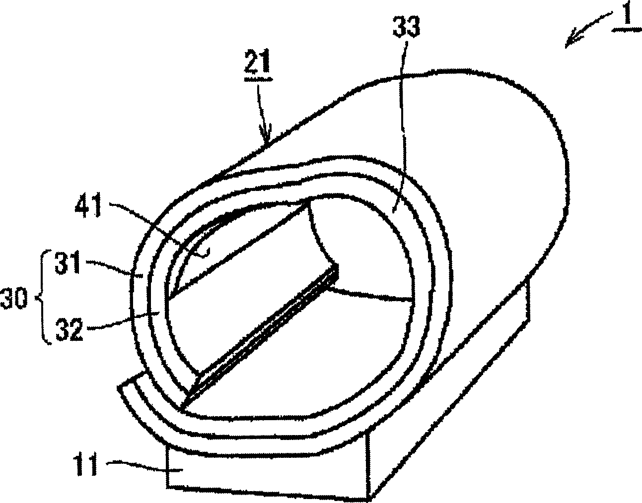
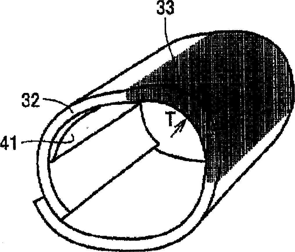
[0028] Refer below figure 1 ~ Fig. 3 illustrates the cuff for the wrist sphygmomanometer of this embodiment. In addition, figure 1 Is a perspective view showing the structure of the wrist sphygmomanometer of this embodiment, figure 2 This is a perspective view of the structure of the ring of the fixing member of the cuff for the wrist-type blood pressure monitor of this embodiment, Figure 3A~Figure 3C A cross-sectional view for explaining the use state of the cuff for the wrist type blood pressure monitor of the present embodiment.

[0029] (Structure of cuff for wrist sphygmomanometer)

[0030] The structure of the cuff for the wrist sphygmomanometer will be described below. Like figure 1 As shown, the sphygmomanometer 1 is formed by integrating the cuff 21 for the wrist sphygmomanometer with the sphygmomanometer body 11. The cuff 21 is composed of a fixing member 30 and a fluid bag 41. The fixing member 30 is composed of a belt 31 and a ring 32. The fluid bag 41 is fixed on...

no. 2 Embodiment

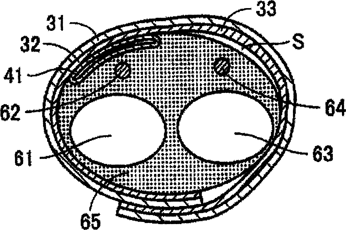
[0050] Refer below Figure 4 Regarding the cuff for the wrist-type blood pressure monitor of this embodiment, only the configuration that is different from the above-mentioned embodiment will be described. In addition, Figure 4 A cross-sectional view for explaining the use state of the cuff for the wrist type blood pressure monitor of the present embodiment.

[0051] Like Figure 4 As shown, in this embodiment, the spacer 35 provided on the inner surface side of the fixing member 30 creates a gap S between the non-selected artery 64 and the fixing member 30. The spacer 35 is formed of, for example, an elastic material such as foamed urethane, and the inner surface thereof has a C-shape so as to extend along the bone 63 of the wrist 65. Because of the structure like this, in the state of wearing the cuff 21, like Figure 4 As shown, the spacer 35 is appropriately deformed, and its inner surface corresponds to the bone 63 of the wrist 65, so that the cuff 21 can be stably fixed, an...

no. 3 Embodiment

[0054] Refer below Figure 5 With FIG. 6, with respect to the cuff for the wrist-type blood pressure monitor of this embodiment, only the configuration different from that of the first embodiment will be described. In addition, Figure 5 This is a perspective view of the cuff for the wrist type sphygmomanometer of this embodiment, Figure 6A , Figure 6B A cross-sectional view for explaining the use state of the cuff for the wrist type blood pressure monitor of the present embodiment.

[0055] In this embodiment, the fixing member 30 is provided with an opening 36. At the wrist 65 where the non-selected artery is located, the proportion of the area directly contacted by the fixing member 30 is smaller than that of the other parts of the wrist 65. The proportion of the area in direct contact. That is, since the fixing member 30 is provided with an opening 36 in the wrist 65 where the non-selected artery is located, the fixing member 30 achieves direct contact only in the part other...


PUM


Abstract

Provide is a wrist type blood pressure meter cuff not oppressing the non-selected artery so as to prevent its pulse waves from mixing into pulse waves of the selected artery necessary for measurement, in a cuff used in a blood pressure meter for measuring blood pressures by selecting and oppressing one artery of the wrist. A wrist type blood pressure meter cuff comprises a fluid bag 41 for oppressing a selected artery of either radial artery or ulnar artery located at the wrist by feeding fluid inside to inflate, and a fixing member 30 for fixing the fluid bag at the wrist. By forming a gap between the fixing member and the wrist, the oppressing pressure directly applied from the fixing member 30 to the wrist at which the non-selected artery is located is set smaller than the oppressing pressure directly applied from the fixing member 30 to other position of the wrist when oppressing the wrist by inflating the fluid bag. This gap is produced by a swollen part 33 provided in the fixing member.

Description

Technical field [0001] The present invention relates to a cuff for a wrist type sphygmomanometer. The cuff for a wrist type sphygmomanometer includes a fluid bag that is injected with fluid such as air, compresses a selected artery of the wrist, and a fluid bag for fixing the fluid bag to the wrist. Fastener. Background technique [0002] At the wrist where the wrist sphygmomanometer is worn, there are two arteries, the radial artery and the ulnar artery, and the wrist sphygmomanometer generally compresses these two arteries when measuring blood pressure. However, the radial artery and the ulnar artery in the wrist are located slightly inward between the two bones called the radius and the ulna and the tendons parallel to them. Therefore, in some users, in the conventional cuff, the compressive force of the fluid bag cannot accurately reach the artery, and the artery cannot be compressed sufficiently. Thus, there is a problem that an accurate blood pressure measurement value cann...

Claims


Application Information

Patent Timeline
Patent Type & Authority Applications(China)
IPC IPC(8): A61B5/022
CPCA61B5/02233
Inventor 井上智纪白崎修佐野佳彦大谷敏夫
Owner OMRON HEALTHCARE CO LTD
Why Eureka
Try Eureka