

Sliding slot heat treatment device
A heat treatment device and heat treatment chamber technology, applied in lighting and heating equipment, furnace components, furnace types, etc., can solve the problems of high heat treatment device height and hot gas leakage.
- Summary
- Abstract
- Description
- Claims
- Application Information
AI Technical Summary
Problems solved by technology
Method used
Image

Examples
Embodiment Construction
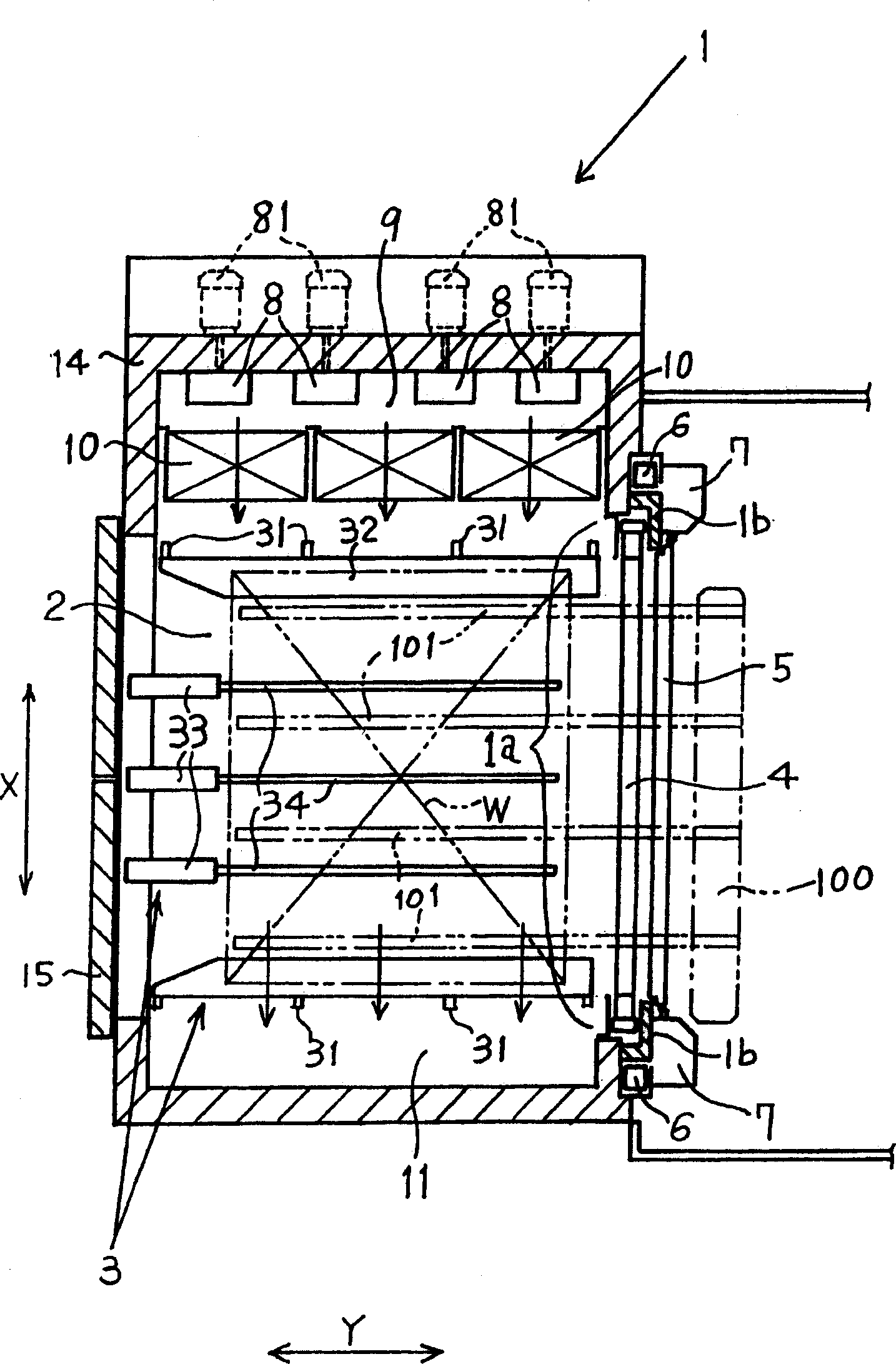
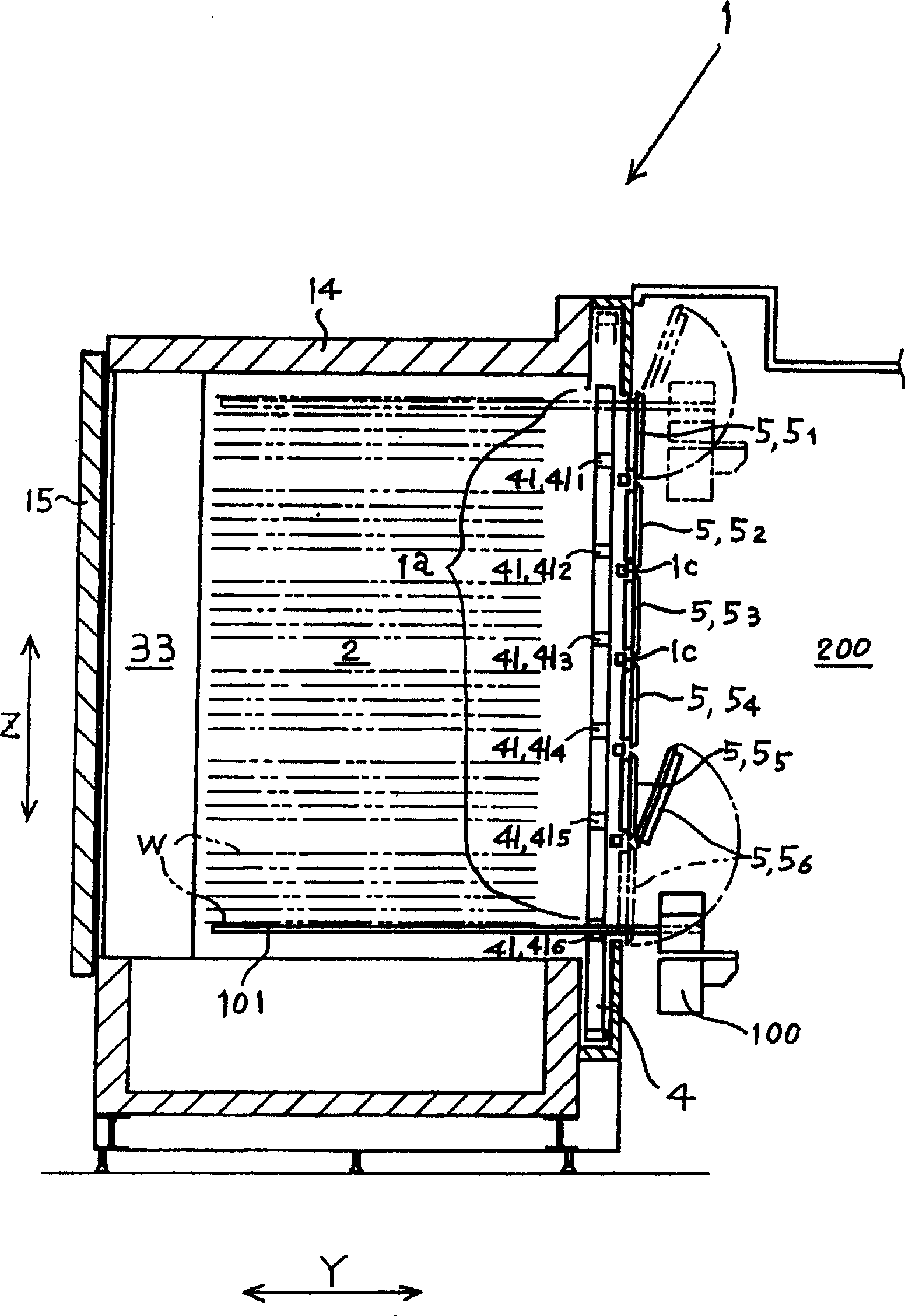
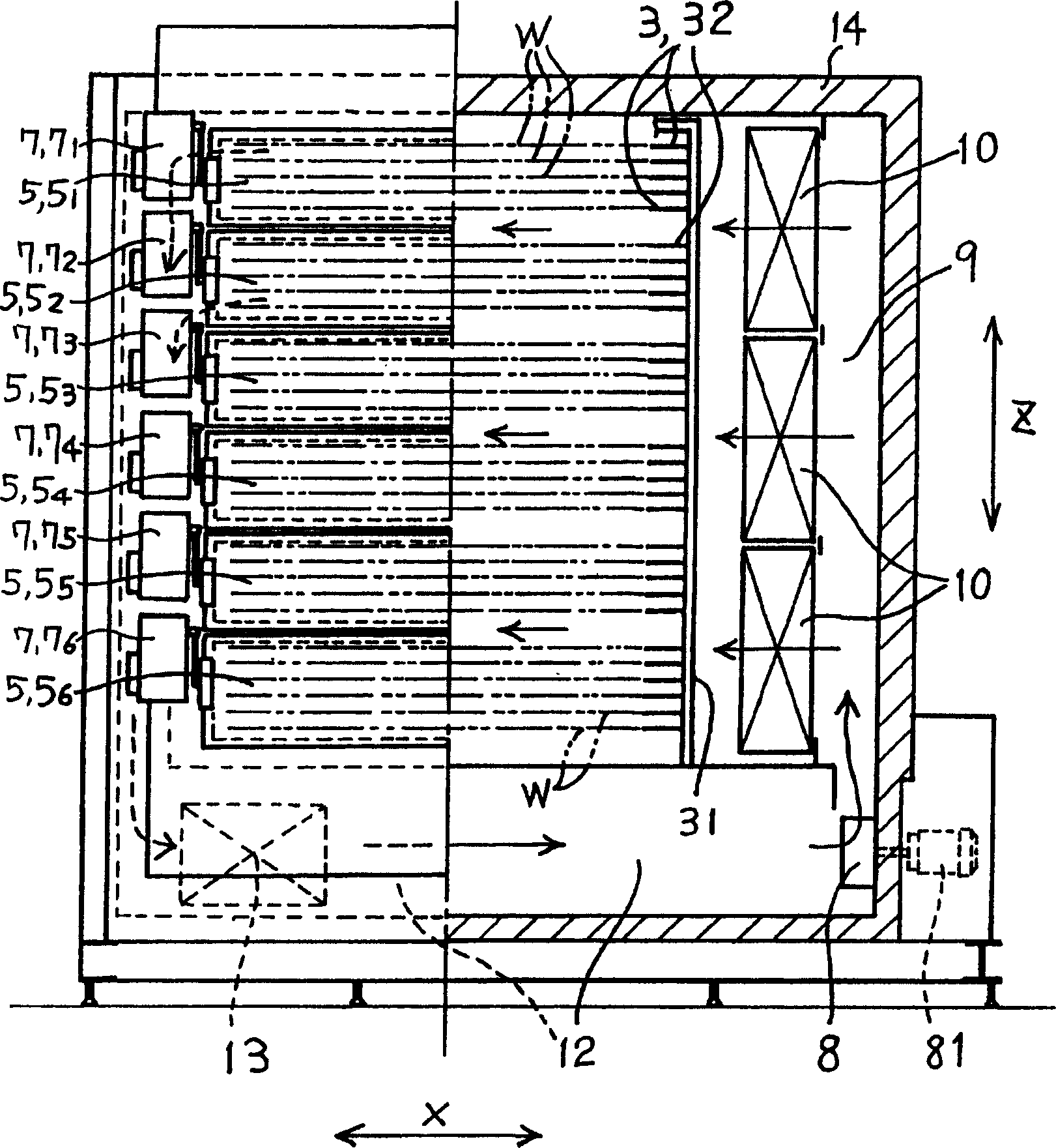
[0030] Figure 1 ~ Figure 3 An example of the overall structure of a heat treatment apparatus commonly called a purification furnace as a heat treatment apparatus to which the present invention is applied is shown.
[0031] The heat treatment apparatus 1 is a kind of workpiece W such as a glass substrate that is processed in a LCD substrate or a PDP manufacturing flow as a flat plate-shaped object to be processed with a support body 3 as a support device installed in the heat treatment chamber 2. , and from the opening face 1a that is formed on one side of the heat treatment chamber as the opening of the heat treatment chamber 2 in this example to take and place the device for heat treatment one by one, wherein as a multilayer, it is 31 layers in this example, and it has as a slit The shielding plate 4, the small door 5, the lifting mechanism 6, and the opening and closing mechanism 7 of the parts.
[0032] There are air-conditioning parts on both sides of the width X directi...
PUM
 Abstract
Description
Claims
Application Information