Fuel injection control method and device of double-fuel internal-combustion engine

A technology of fuel injection and control device, which is applied in the directions of fuel injection device, fuel injection control, low-pressure fuel injection, etc., can solve the problems of increasing the cost of fuel supply device and the like

Inactive Publication Date: 2004-08-04
HITACHI LTD
View PDF1 Cites 28 Cited by
  • Summary
  • Abstract
  • Description
  • Claims
  • Application Information

AI Technical Summary

Problems solved by technology

[0007] In addition, compared with conventional gasoline internal combustion engines, since two fuel injection devices are provided for one internal combustion engine, that is, for gas fuel and for liquid fuel, the cost of the fuel supply device increases, so reducing the cost of the fuel supply device becomes a problem.

Method used


Image

  • Fuel injection control method and device of double-fuel internal-combustion engine
  • Fuel injection control method and device of double-fuel internal-combustion engine
  • Fuel injection control method and device of double-fuel internal-combustion engine

Examples


Embodiment Construction

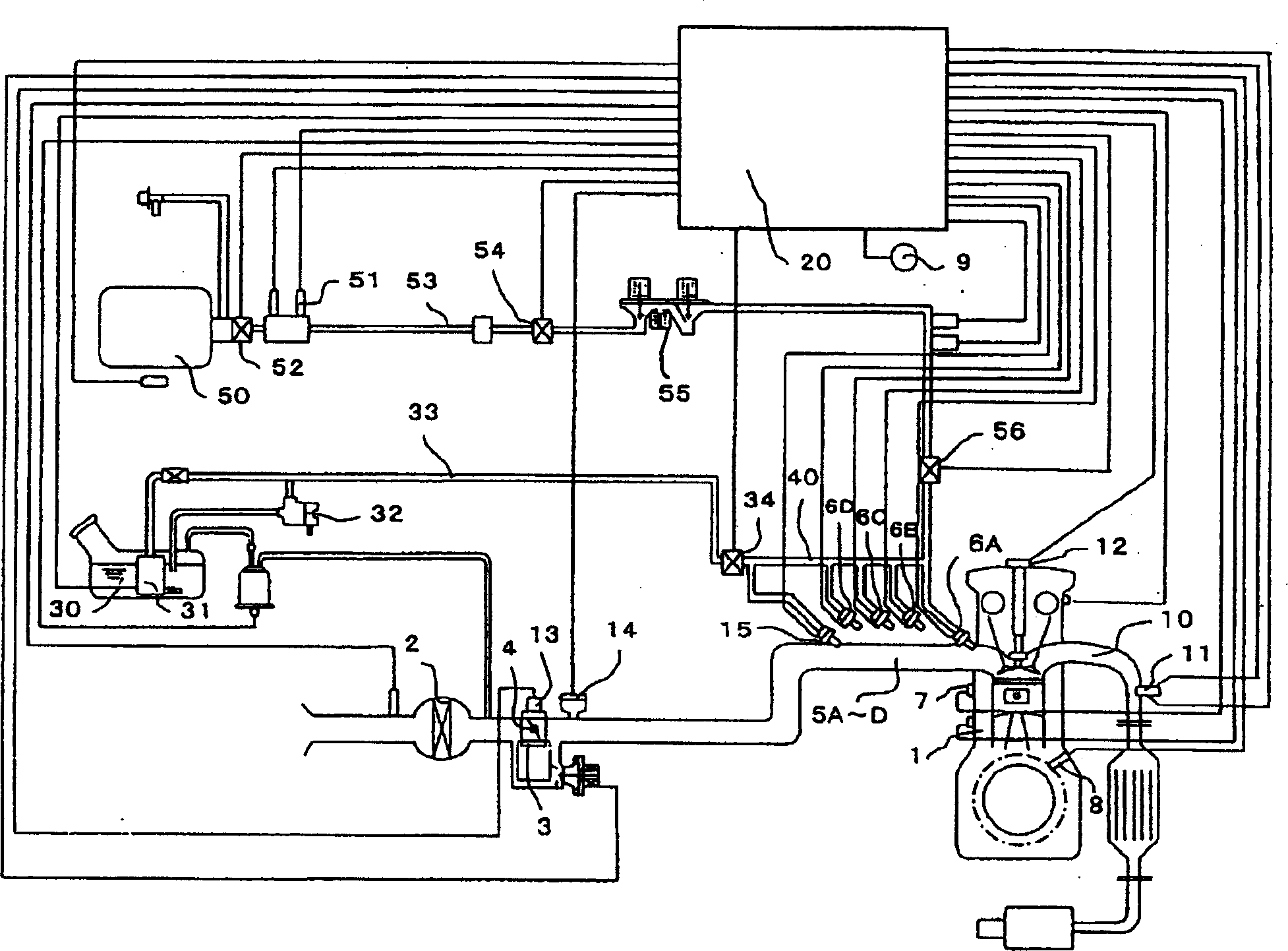
[0018] The embodiments of the present invention will be described below. figure 1 It is a structural diagram of the system to which the present invention is applied.

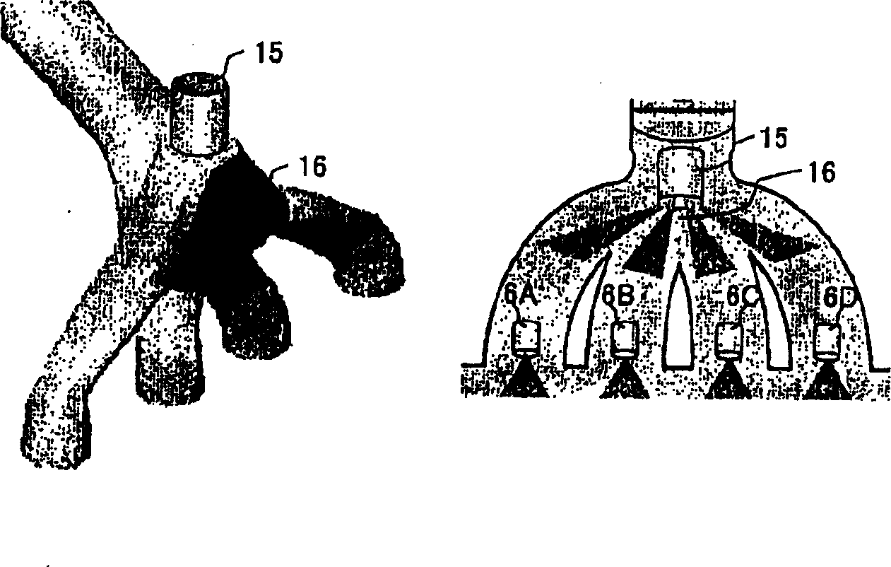
[0019] figure 1 This is a structural diagram of a system to which the fuel injection device of the present invention is applied. The intake pipes 5A to 5D are provided with gas and liquid fuel injection valves 6A to 6D for injecting fuel. A throttle body 3 is provided upstream of the throttle valve body 3, and a throttle valve 4 is accommodated. In order to detect the load state of the internal combustion engine 1, a throttle valve opening sensor 13 and an intake pipe negative pressure sensor 14 are provided.

[0020] The gas and liquid fuel injection valves 6A to 6D have a structure in which fuel is introduced from the upper part and injected from the orifice at the tip. The fuel is metered by the orifice provided on the movable valve and the nozzle that are moved up and down by electromagnetic force. injection....


PUM


Abstract

A bi-fuel internal combustion engine is intended for suppressing consumption of gasoline fuel and reducing exhaust emissions; under ordinary operations, a CNG fuel emitting smaller amounts of NOx, HC, CO, and the like as compared with a gasoline fuel, is used as a supply fuel to reduce the exhaust emissions; in this case, a fuel injection device is required for each of the two types of fuel, that is, the gasoline fuel and the CNG fuel and the problem is torque change and fluctuation occurring when the fuel is switched from gasoline to CNG, or vice versa. Control is provided for correcting a fuel injection quantity, an intake air quantity, and ignition timing when the type of fuel supplied to the engine is switched from one type to another. A single fuel injector is used as both an injector of gasiform fuel and an injector of liquid fuel.

Description

Technical field [0001] The present invention relates to an internal combustion engine of a so-called dual-fuel vehicle that operates on two or more fuels such as gasoline and CNG (liquefied natural gas), and to a fuel injection device. Background technique [0002] The main purpose of dual-fuel internal combustion engines is to suppress the consumption of gasoline fuel and reduce the accompanying emissions. The fuel used is, for example, a combination of gasoline and CNG (Compressed Nature Gas) as described in Japanese Patent Application Publication No. 2002-38986. [0003] During normal operation, the NO emitted compared with gasoline fuel x , HC, CO and other low CNG fuels are used as supply fuels to reduce emissions. [0004] In this case, since the fuel injection device requires gasoline and CNG respectively, two fuel injection devices are required for an internal combustion engine. [0005] Patent Document 1: Japanese Patent Application Publication No. 2002-38986 [0006] In...

Claims


Application Information

Patent Timeline
Patent Type & Authority Applications(China)
IPC IPC(8): F02P5/15F01N3/20F02D9/02F02D19/06F02D19/08F02D37/02F02D41/00F02D41/04F02D43/00F02D45/00F02M21/02F02M37/00F02M61/04F02M69/04F02P5/152
CPCF02B2275/16F02P5/1506F02D2200/0404F02D19/0615F02D41/187F02M21/0278Y02T10/123F02D19/061F02D19/0681F02D19/081F02D2200/023Y02T10/32F02D41/0027F02P5/1521F02D19/0692F02D37/02F01N3/20F02D2250/21F02D19/0694F02M69/044F02D19/0647Y02T10/12Y02T10/30
Inventor 中野泰之永野正美天野松男
Owner HITACHI LTD
Why Eureka
Try Eureka