
Turbine for driving fast rotary tool

A technology of rotating tools and turbines, which is applied in the field of turbines of fast rotating tools and can solve problems such as generating braking effects

Inactive Publication Date: 2004-08-11
GAT GES FUR ANTRIEBSTECHN
View PDF0 Cites 8 Cited by
  • Summary
  • Abstract
  • Description
  • Claims
  • Application Information

AI Technical Summary

Problems solved by technology

In any case the paint being directed to the spray dome has to be accelerated through the spray dome so obviously this has a braking effect

Method used


Image

  • Turbine for driving fast rotary tool
  • Turbine for driving fast rotary tool
  • Turbine for driving fast rotary tool

Examples


Embodiment Construction

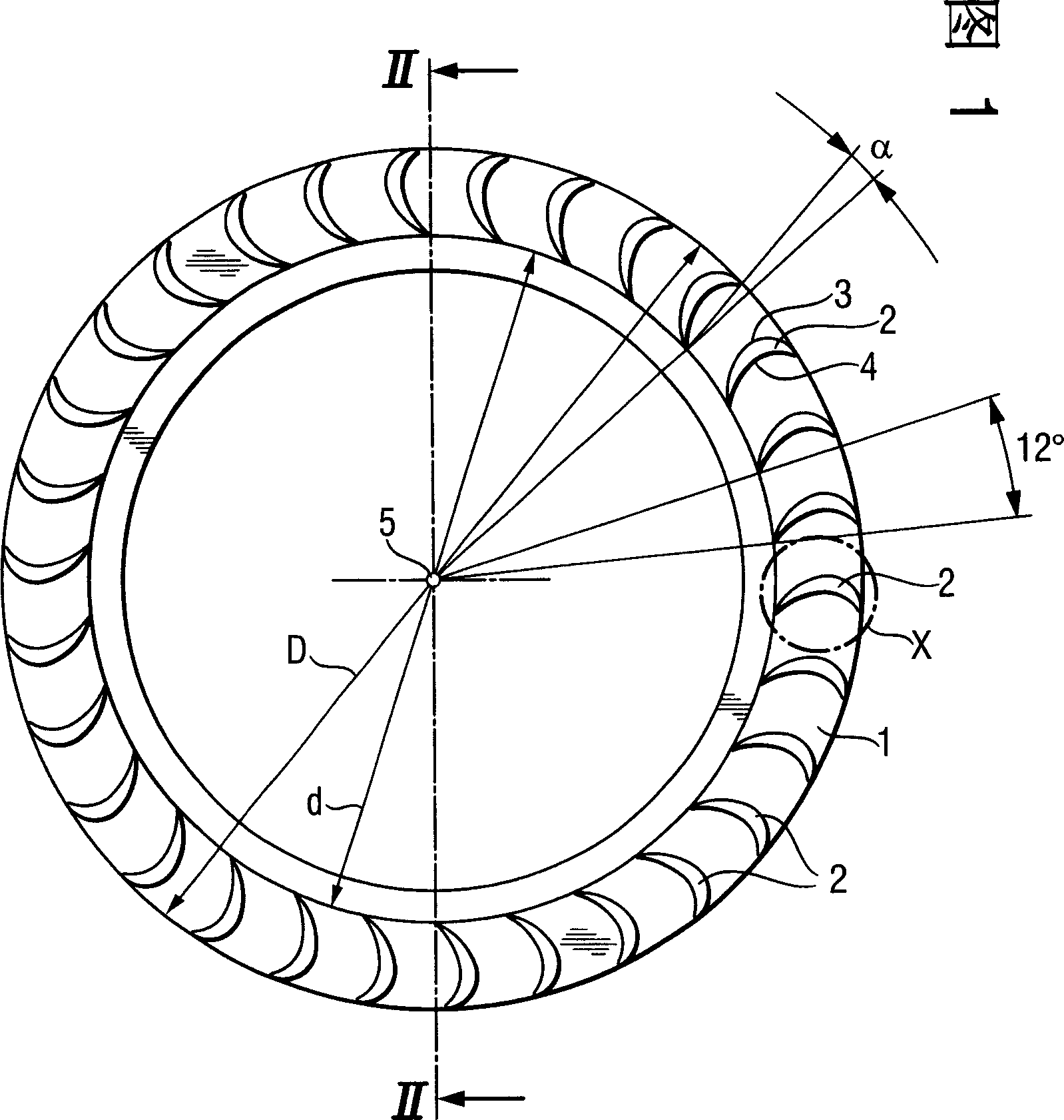
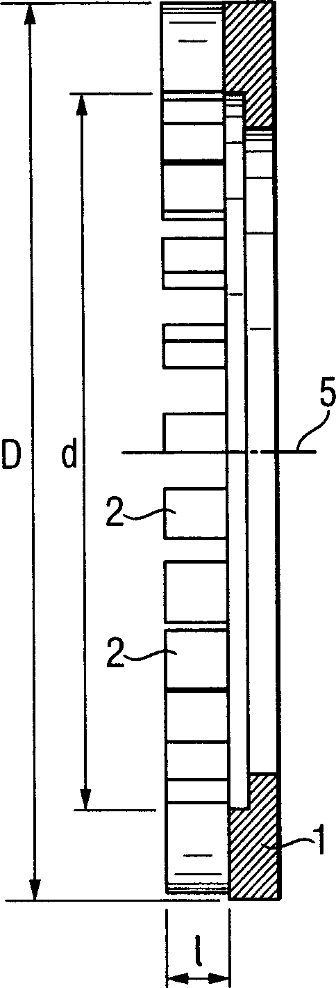
[0026] FIG. 1 shows a turbine with a disc-shaped carrier plate 1 having an outer diameter D. As shown in FIG. On the outer edge of the carrier plate 1 is a circle of turbine blades 2. As shown in FIG. 2, the outer edge of the turbine blade 2 is roughly located at the position of diameter D, while the diameter of the inner edge of the blade ring is d. Specifically, the value of d is between 40 and 44 mm, the value of D is between 50 and 60 mm, and the difference between D-d is about 20% of D. The corresponding radius is half of the corresponding value.

[0027] As also shown in FIG. 1 , the individual blades are inclined forward relative to the radial direction by an angle α, that is to say such that the outer edge of the turbine blade is slightly ahead of the inner edge in the direction of rotation R. In particular, the angle α, ie the angle of the line joining the outer and inner edges of the blade with respect to the radius vector to the inner edge of the blade, is approxim...


PUM


Abstract

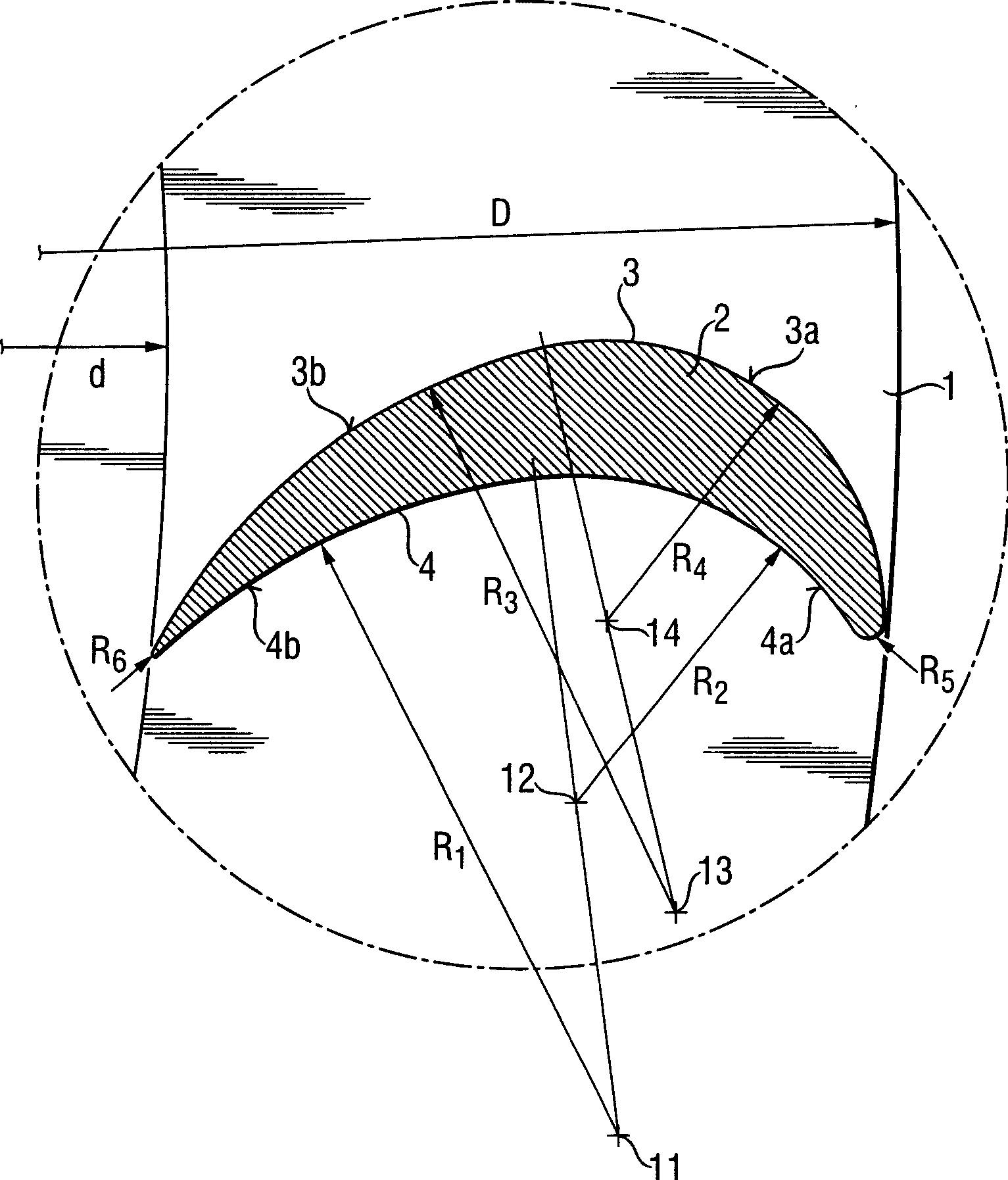
The turbine wheel has blades (2) with axially parallel front and rear surfaces (3, 4) and are radially curved. The radially outer sectors of the front surface (3a, 4a) are of smaller curve radius (R2, R4) than the inner sectors (3b, 4b). The front surface, at least in sectors, has a smaller curve radius than the rear surface.

Description

technical field [0001] The present invention relates to a turbine for driving a fast rotating tool, in particular a rotating disk and / or dome turbine for a painting installation, the turbine having a disk or annular bearing plate, which is held by It is installed to be rotatable around an axis, and a circle of turbine blades is arranged on it, and these turbine blades have axially parallel fronts and backs, and these blades are curved in radial direction, that is, curved in a direction perpendicular to the axis of the turbine, and the front The radius of curvature of at least some portions of the rear face is smaller than that of the rear face. [0002] In this context, "front" is to be understood as meaning the surface of the turbine blade located in front in the direction of rotation of the turbine, and accordingly "rear side" is understood to mean the surface of the blade located behind in the direction of rotation of the turbine. Background technique [0003] Correspond...

Claims


Application Information

Patent Timeline
Patent Type & Authority Applications(China)
IPC IPC(8): B05B3/10F01D1/06F01D5/04F01D5/14F01D15/06F03B13/04F03D9/00
CPCF03B13/04Y10S416/02Y10S416/05B05B3/1035F05B2240/301F05B2250/314F01D15/06F05B2250/71F05D2250/71F05D2240/301F01D5/141F03D9/00Y02E10/72F05D2250/314F01D1/06Y02E10/721F03D9/20
Inventor B·施米特
Owner GAT GES FUR ANTRIEBSTECHN
Learn More