Electric steering lock apparatus with overheat protection

An electronic control and actuator technology, which is applied to anti-theft vehicle accessories, instruments, building locks, etc., can solve the problems of increasing manufacturing costs and increasing manipulation and locking equipment

Inactive Publication Date: 2004-08-18
KK TOKAI RIKA DENKI SEISAKUSHO
View PDF1 Cites 2 Cited by
  • Summary
  • Abstract
  • Description
  • Claims
  • Application Information

AI Technical Summary

Problems solved by technology

Therefore, using such a motor equipped with an overheating protection function will increase the manipulation of the locking device and increase the manufacturing cost

Method used


Image

  • Electric steering lock apparatus with overheat protection
  • Electric steering lock apparatus with overheat protection
  • Electric steering lock apparatus with overheat protection

Examples


Embodiment Construction

[0016] An electronically operated locking device 1 according to a preferred embodiment of the present invention will now be described with reference to the accompanying drawings.

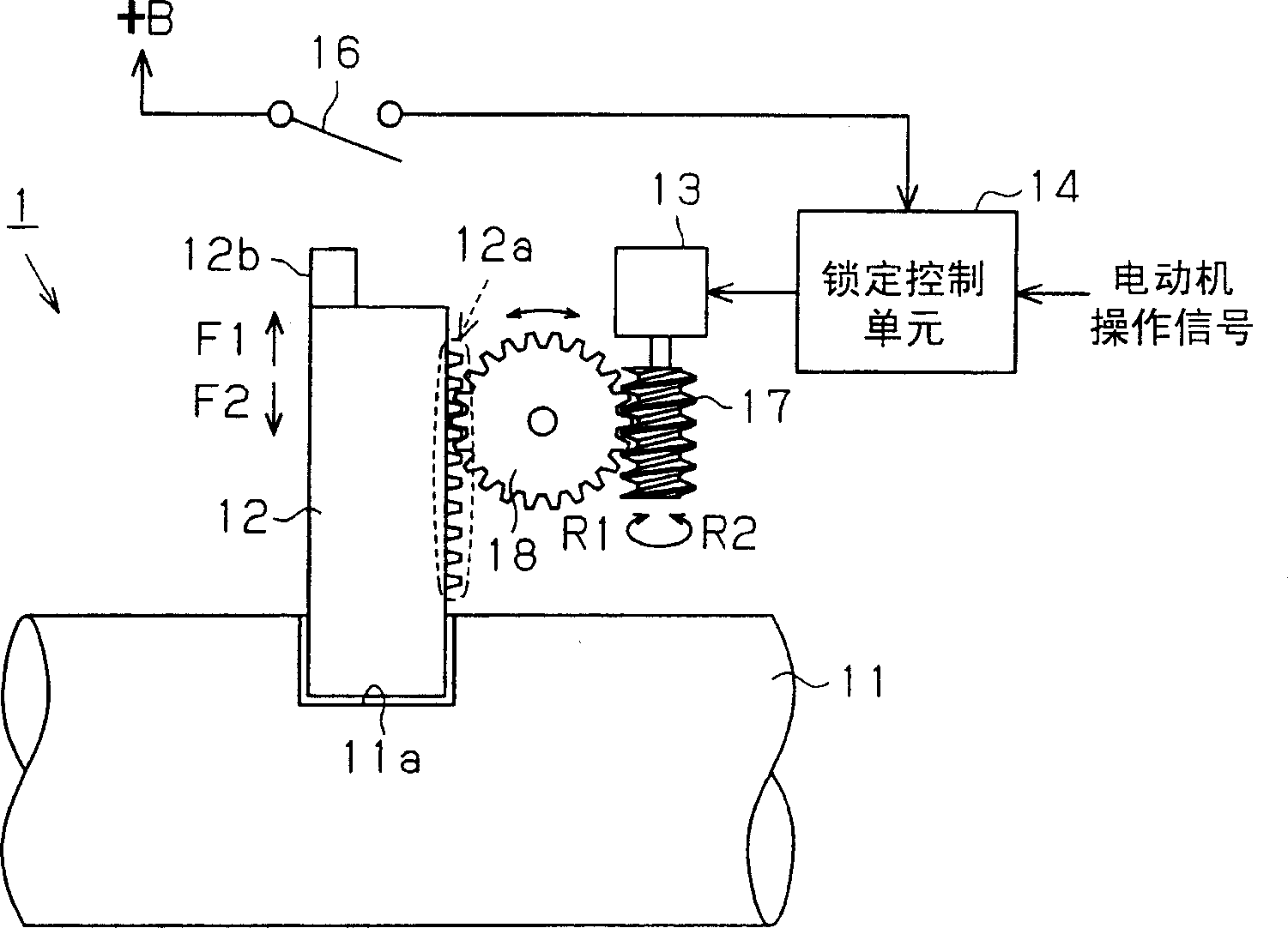
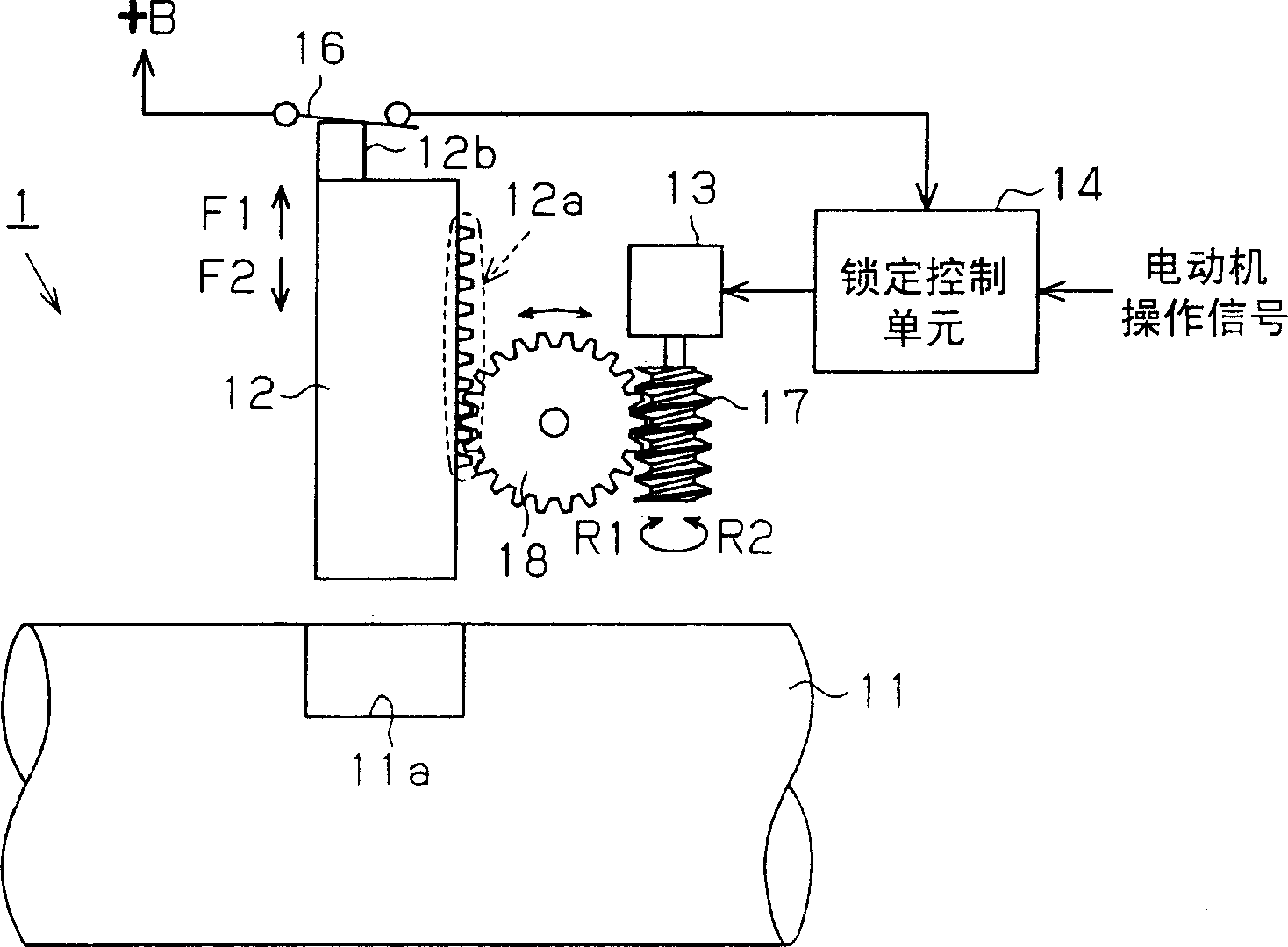
[0017] refer to Figure 1(a) and 1(b) , the electronically manipulated locking device 1 includes a manipulation shaft 11 , a lock pin 12 , an electric motor 13 serving as an actuator, and a lock control unit 14 . The lock control unit 14 is connected to a detection switch 16 . In the preferred embodiment, the detection switch 16 is preferably a normally open (contact type) mechanical switch (limiting the switches of this preferred embodiment). One end of the detection switch 16 is connected to the positive pole of the battery and the other end is connected to the locking control unit 14 .

[0018] The lock control unit 14 controls the motor 13 with a drive signal and drives the motor 13 . The motor 13 has a rotating shaft fixed to the worm wheel 17 . The worm wheel 17 is in rotational mesh with...


PUM


Abstract

An electric steering lock apparatus that protects an actuator from overheating without enlarging the actuator. The electric steering lock apparatus includes a lock pin engaged with a steering shaft to lock the steering shaft. An actuator moves the lock pin between a lock position in which the lock pin is engaged with the steering shaft and an unlock position in which the lock pin is disengaged from the steering shaft. A control unit controls the actuator. The control unit generates a calculated value related to operation time of the actuator and suspends operation of the actuator when the calculated value is greater than a predetermined operation suspension threshold value.

Description

technical field [0001] The present invention relates to an electronically operated locking device, and more particularly to an electronically operated locking device that protects an actuator from overheating. Background technique [0002] Typically, mechanically operated locking devices are used to prevent theft of automobiles. [0003] Japanese Laid-Open Patent No. 11-105673 describes a mechanically operated locking device with a key cylinder. Inserting the key into the key cylinder and turning the key moves the lock pin into engagement with and out of the steering shaft. Engagement of the locking pin with the steering shaft locks the steering shaft and limits rotation of the steering shaft. This rotation restriction increases the safety of the car with car thieves in mind. [0004] In recent years, in order to improve the mobility of vehicles, a one-push type engine start / stop system with a key switch for starting and stopping the engine has appeared. In the steering ...

Claims


Application Information

Patent Timeline
Patent Type & Authority Applications(China)
IPC IPC(8): B60R25/0215
CPCB60R25/02153Y10T70/7006G06F1/1601G06F1/1613
Inventor 深野裕司田中贤次森密雄舟山友幸柳生干人挂川智央
Owner KK TOKAI RIKA DENKI SEISAKUSHO
Why Eureka
Try Eureka