Method and system for reducing engine exhaust emissions

A technology of engine and organic matter, applied in the direction of engine components, combustion engine, engine control, etc., can solve the problems of fuel economy degradation

Inactive Publication Date: 2016-10-26
FORD GLOBAL TECH LLC
View PDF11 Cites 6 Cited by
  • Summary
  • Abstract
  • Description
  • Claims
  • Application Information

AI Technical Summary

Problems solved by technology

As another example, after the upstream addition of ionized air, the engine may need to r

Method used


Image

  • Method and system for reducing engine exhaust emissions
  • Method and system for reducing engine exhaust emissions
  • Method and system for reducing engine exhaust emissions

Examples


Embodiment Construction

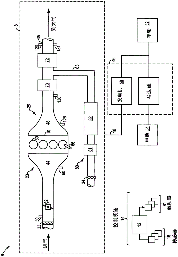
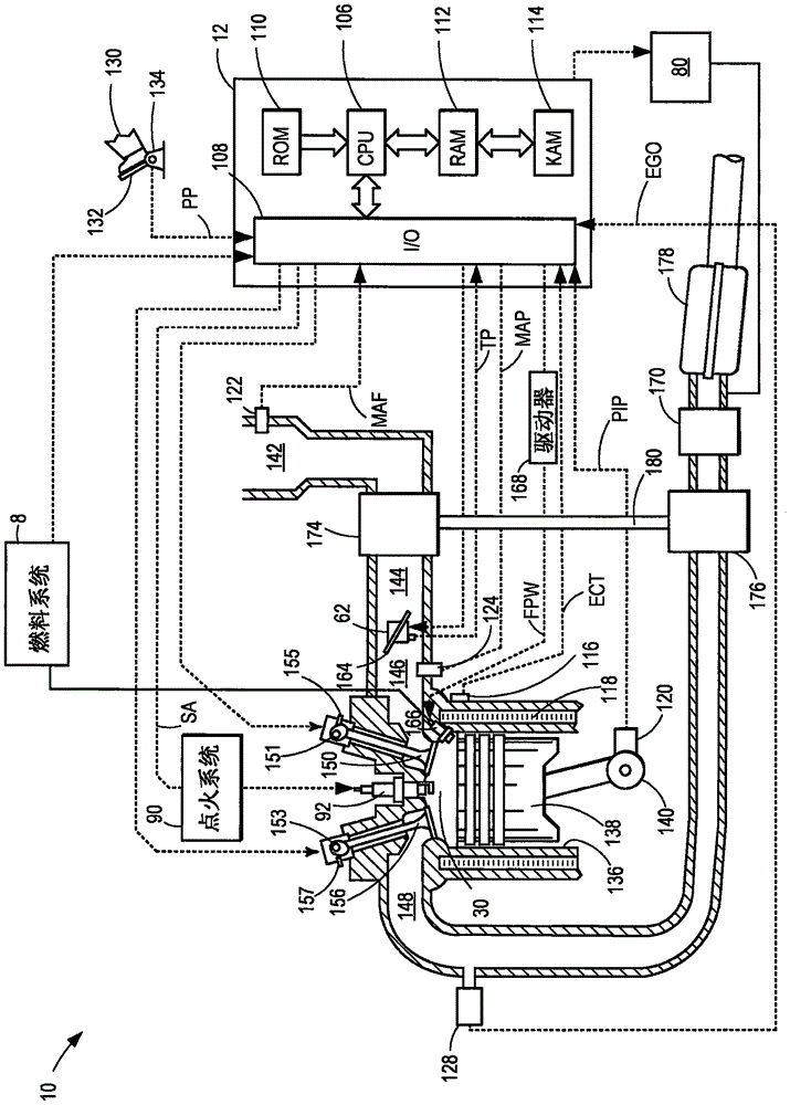
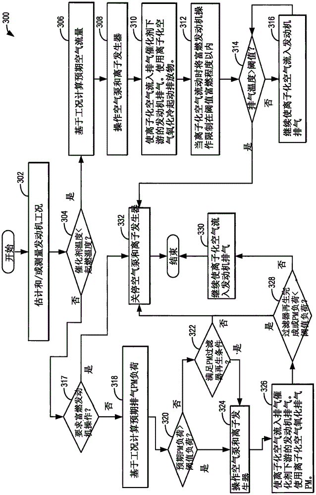
[0015] The present application provides the use of ionized air to treat Figure 1-2 A method and system for cold start emissions and particulate emissions. The engine controller can be configured to execute control programs such as image 3 The example routine in to flow ionized air into engine exhaust downstream of an exhaust oxidation catalyst and upstream of an exhaust particulate filter based at least on catalyst temperature. Cold start emissions that are not oxidized by the oxidation catalyst are oxidized by the ionized air, thereby reducing exhaust emissions. Additionally, ionized air may be used to reduce PM emissions during other conditions when particulate matter (PM) emissions from the engine are high, thereby reducing reliance on exhaust particulate filters. Then, the organic matter oxidized by the ionized air can be exhausted through the exhaust tailpipe. refer to Figure 4 An example cold start operation is shown. In this way, engine exhaust emissions complia...


PUM


Abstract

Methods and systems are provided for addressing engine cold-start emissions while an exhaust catalyst is activated. In one example, a method for improving exhaust emissions may include flowing ionized air into an engine exhaust, downstream of an exhaust catalyst, to oxidize exhaust emissions left untreated by the catalyst. The approach reduces the PM load of the exhaust as well as of a downstream particulate matter filter.

Description

technical field [0001] The present description generally relates to methods and systems for reducing engine cold start exhaust emissions and particulate matter emissions. Background technique [0002] Engine-out cold-start emissions generated prior to ignition of an exhaust system emission control device (eg, a catalytic converter) can account for a majority of total exhaust emissions. Various schemes may be used by the engine control system to expedite reaching the catalyst light-off temperature. For example, expensive electrocatalyst heaters can be used to generate heat. As another example, various combinations of spark timing retard, valve overlap, and increased fuel injection may be used to accelerate catalyst warm-up. [0003] In another approach shown by Shimoda in US Pat. No. 7,331,170, the plasma generator is coupled to the emission control device downstream of the oxidation catalyst and upstream of the diesel particulate filter. The exhaust flow is discharged by ...

Claims


Application Information

Patent Timeline
IPC IPC(8): F01N3/22
CPCF01N3/22F01N2900/1626B01D53/92B01D53/9418B01D2251/11B01D2257/702B01D2258/012B01D2259/122F01N3/021F01N3/30F01N3/306F01N3/323F01N9/002F01N2240/28F01N2430/06F01N2550/14F01N2900/1602Y02T10/12Y02T10/40Y02A50/20B01D53/9431B01D53/944B01D53/94F01N3/103F02D41/064F02P5/15
Inventor D·R·马丁K·J·米勒M·J·V·尼乌斯塔特J·E·罗林格
Owner FORD GLOBAL TECH LLC
Why Eureka
Try Eureka