Electrical Switching System

A technology of electrical switch and electrical connection, which is applied in the field of electrical switch system of swirling arc type, and can solve problems such as ineffective cooling of arc columns, deterioration of recovery voltage tolerance, short circuit between plates, etc., and achieves low overall height, reduced quantity, and reduced The effect of length

Active Publication Date: 2022-04-15
ABB (SCHWEIZ) AG
View PDF8 Cites 0 Cited by
  • Summary
  • Abstract
  • Description
  • Claims
  • Application Information

AI Technical Summary

Problems solved by technology

Therefore, a short rear arc column will not be able to cool effectively
Additionally, molten craters and droplets from the surface of the manifold can cause shorts between plates
Therefore, at higher currents (typically greater than 5kA to 10kA), the gap between the plates must increase, resulting in degraded recovery voltage withstand

Method used


Image

  • Electrical Switching System
  • Electrical Switching System
  • Electrical Switching System

Examples


Embodiment Construction

[0039] The inventive concept will now be described more fully hereinafter with reference to the accompanying drawings, in which exemplary embodiments are shown. However, inventive concepts may be embodied in many different forms and should not be construed as limited to the embodiments set forth herein; rather, these embodiments are provided by way of example so that this disclosure will be thorough and complete, and will The scope of the inventive concept fully conveys to those skilled in the art. Throughout this specification, like numbers refer to like elements.

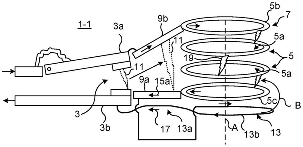
[0040] figure 1 An example of an electrical switching apparatus 1-1 is shown. The electrical switching device 1-1 comprises a main contact arrangement 3 comprising a movable contact 3a and a fixed contact 3b.

[0041] The movable contact 3a is configured to actuate between a closed position in which the movable contact 3a is in mechanical contact with the fixed contact 3b and an open position in which the movab...


PUM


Abstract

An electrical switching device (1-1), comprising: a main contact arrangement (3), comprising fixed contacts (3b) and movable contacts (3a); a plurality of distributor plates (5, 5b, 5c), each Each splitter plate has a loop structure (5a), and the splitter plates (5, 5b, 5c) are coaxially stacked with respect to their loop structure (5a) to form a splitter plate stack (7), wherein the splitter plate stack (7) One of the manifolds (5b) of the manifold is the first outermost manifold (5b), and the other manifold (5c) of the manifold stack (7) is the second outermost manifold (5c); the first arc runner (9a) and the second arc runner (9b), the first arc runner (9a) is electrically connected to the second outermost splitter plate (5c), the second arc runner (9b) is electrically connected to the first outermost splitter plate (5b), the first arc runner (9a) and the second arc runner (9b) are configured to displace the main arc (11) from the main contact ( 3) directed to the splitter plate stack (7), thereby splitting the primary arc (11) into multiple secondary arcs (19) between the splitter plates (5, 5b, 5c); and the first drive coil (13), driven by Electrically connected to the second arc roller (9b) and the movable contact (3a) or the first arc roller (9a) and the fixed contact (3b), wherein the first driving coil (13) has The first force increasing coil part (13) extending parallel to the first arc runner (9a) in the direction of 7), so that the first force increasing coil part (13a) can be in contact with the first arc runner (9a) The main current flows in the same direction and in parallel with the main current flow in the first arc runner (9a) carrying current (17) to increase the magnetic field, thereby increasing the The Lorentz force of the primary arc (11) between the roller rings (9b), the first drive coil (13), when energized, is configured to create a blowing magnetic field in the splitter plate stack (7), resulting in a secondary The arc (19) moves circumferentially along the loop structure (5a) of the splitter plate (5, 5b, 5c).

Description

technical field [0001] The present disclosure generally relates to electrical switching systems for extinguishing electric arcs. In particular, it relates to an electrical switching system of the swirling arc type. Background technique [0002] When the current is interrupted, either in an AC system with natural zero crossings or in a DC system with zero crossings caused by injected current, the recovery voltage will occur on the back arc. The traditional solution to this problem is to introduce an arc chamber with several splitter plates where the arc entering the arc chamber from the main contacts will be divided into several short arcs for efficient cooling to withstand rapid rise recovery Voltage. [0003] On a traditional manifold, the arc is only allowed to travel a short distance. Consequently, they become stationary and thus cause severe melt damage on the surface of each manifold. This melting has several negative consequences. For example, metal vapor in the r...

Claims


Application Information

Patent Timeline
Patent Type & Authority Patents(China)
IPC IPC(8): H01H9/36H01H9/44H01H73/18
CPCH01H9/36H01H9/446H01H73/18H01H2009/365H01H2009/367H01H33/185H01H33/42H01H33/53
Inventor 张自驰斯蒂芬·瓦德玛森
Owner ABB (SCHWEIZ) AG
Why Eureka
Try Eureka