Combustion control device for an engine

A control device and engine technology, applied in the direction of engine control, automatic control, automatic control, etc., can solve problems such as reduction, cost increase, and fuel consumption rate reduction.

Inactive Publication Date: 2004-08-18
ISUZU MOTORS LTD
View PDF6 Cites 17 Cited by
  • Summary
  • Abstract
  • Description
  • Claims
  • Application Information

AI Technical Summary

Problems solved by technology

Although after-treatment devices can be used to purify soot and NOx, it leads to lower fuel consumption and higher costs
[0020] In addition, in the premixed combustion of the above-mentioned single-stage injection, if the EGR is increased, the oxygen concentration will decrease and the flame will be more easily stalled. Therefore, the NOx reduction effect of EGR cannot be sufficiently obtained.

Method used


Image

  • Combustion control device for an engine
  • Combustion control device for an engine
  • Combustion control device for an engine

Examples


Embodiment Construction

[0036] Hereinafter, an embodiment of the present invention will be described with reference to the drawings.

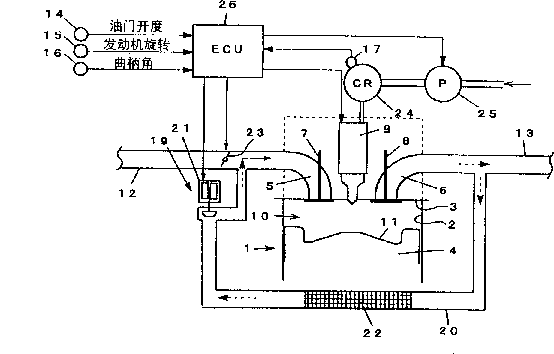
[0037] This embodiment is suitable for common rail direct injection diesel engines, refer to figure 1 The schematic structure will be described. figure 1 Only one cylinder is shown in , of course, there may be multiple cylinders.

[0038]Among the figure, 1 is engine body, is made of cylinder 2, cylinder head 3, piston 4, suction port 5, exhaust port 6, suction valve 7, exhaust valve 8, injector 9 etc. In the space between the cylinder 2 and the cylinder head 3, a combustion chamber 10 is formed. Fuel is directly injected into the combustion chamber 10 from the injector (combustion injection valve) 9 . A cavity 11 is formed at the top of the piston 4 as a part of the combustion chamber 10 . The cavity 11 is formed in the form of a concave combustion chamber with a raised bottom center. The injector 9 is arranged substantially coaxially with the cylinder 2, and in...


PUM


Abstract

A combustion control device for an engine, comprises a fuel injection valve (9) for injecting a fuel into a combustion chamber (10), ignition timing adjustment unit (19) for adjusting an ignition timing of a mixture inside the combustion chamber (10), and control unit (26) for controlling the fuel injection valve (9) and the ignition timing adjustment unit (19). The control unit (26) controls the fuel injection valve (9) so as to execute at least a first injection which is conducted within the interval from an intake stroke to a compression stroke and a second injection conducted in the vicinity of a compression top dead center after the execution of the first injection, and controls the ignition timing adjustment means (19) so that the mixture formed by a fuel injected by the first injection and second injection and an intake air or the like is ignited after completion of the injection of the second injection.

Description

technical field [0001] The present invention relates to a combustion control device of an engine, and particularly relates to a combustion control device of an engine capable of performing premixed combustion which greatly reduces NOx and smoke dust in a wider operating range. Background technique [0002] Conventionally, in a diesel engine, when the cylinder (combustion chamber) reaches high temperature and high pressure, that is, when the piston is near compression top dead center, fuel is injected for combustion. [0003] The injected fuel is mixed with the intake air to form an air-fuel mixture, which is ignited to form a flame, and the injected fuel is continuously supplied to the flame to continue combustion. This combustion method starts ignition during fuel injection, and is referred to as normal combustion in this specification. [0004] In recent years, a new combustion method (such as Japanese Patent Documents 1 and 2) has been proposed. This combustion method ad...

Claims


Application Information

Patent Timeline
Patent Type & Authority Applications(China)
IPC IPC(8): F02P5/15F02B1/12F02B3/06F02B7/02F02B23/00F02B23/06F02B47/08F02D13/02F02D15/00F02D15/04F02D19/08F02D21/08F02D37/02F02D41/00F02D41/04F02D41/30F02D41/40F02D43/00F02M25/00F02M25/022F02M25/07F02M45/04F02M47/00F02M51/00
CPCF02D41/402F02D2041/001Y02T10/123F02B47/08F02M25/03Y02T10/47F02D19/0689F02M25/0727F02D19/081F02D15/04F02D41/0057F02B3/06Y02T10/18F02B1/12Y02T10/44F02D13/0207F02D41/3035F02D41/3047F02D37/02F02D19/0655F02B2275/14F02M26/23Y02T10/12Y02T10/30Y02T10/40
Inventor 岛崎直基
Owner ISUZU MOTORS LTD
Why Eureka
Try Eureka