
Multistage depressed collector structure of traveling wave tube and traveling wave tube

A collector and traveling wave tube technology, which is applied in the field of vacuum microwave electronic devices, can solve the problems of poor secondary electron suppression of backflow, easy formation of backflow, and low collector efficiency, so as to avoid processing and assembly and improve recovery efficiency , The effect of high collection and recycling efficiency

Pending Publication Date: 2022-05-17
山东微波电真空技术有限公司
View PDF0 Cites 0 Cited by
  • Summary
  • Abstract
  • Description
  • Claims
  • Application Information

AI Technical Summary

Problems solved by technology

[0003] From the perspective of the electron trajectory, under the axisymmetric structure, some primary electrons are decelerated to zero after the multi-stage step-down collector, and are reversely accelerated back to the interaction area because they do not hit the electrode; in addition, some primary electrons are in the When hitting the fourth-level electrode, whether it is the true secondary electrons generated or the primary electrons that undergo elastic scattering, these secondary electrons move along the axial direction, and are easy to form backflow after being accelerated by the electric field, resulting in low collector efficiency. Poor suppression of secondary electron backflow

Method used


Image

  • Multistage depressed collector structure of traveling wave tube and traveling wave tube
  • Multistage depressed collector structure of traveling wave tube and traveling wave tube
  • Multistage depressed collector structure of traveling wave tube and traveling wave tube

Examples


Embodiment 1

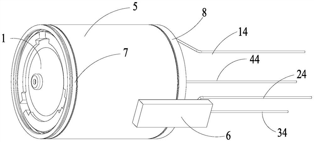
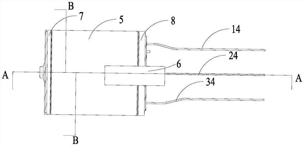
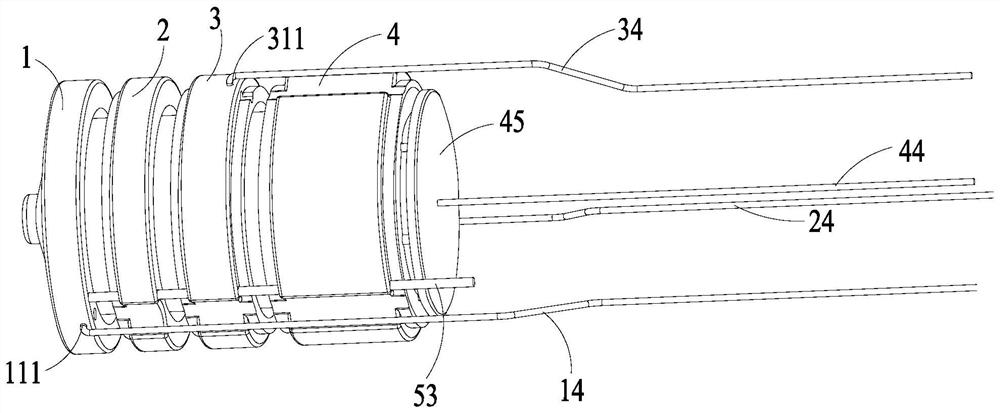
[0055] The invention provides a traveling wave tube multi-stage step-down collector structure, such as Figure 1-Figure 4 As shown, the collector structure includes an outer cylinder 5 having a housing chamber 51, a first collector assembly 1 and a second collector assembly arranged in the housing chamber 51 and sequentially distributed along the axial direction of the outer cylinder 5 2. The third collector assembly 3 and the fourth collector assembly 4, the collector structure also includes a plurality of insulating ceramics 52 arranged along the inner wall of the outer cylinder 5, and the inner wall of the insulating ceramics 52 is provided with The limiting part 521 cooperates with the first collector assembly 1 , the second collector assembly 2 , the third collector assembly 3 and the fourth collector assembly 4 . The first collector assembly 1 , the second collector assembly 2 , the third collector assembly 3 and the fourth collector assembly 4 respectively have a first ...

Embodiment 2

[0076] The present invention also provides a traveling wave tube (not shown in the figure), which includes the collector structure described in Embodiment 1, and also includes an emitter structure, a radio frequency input structure, a radio frequency output structure, for connecting the emitter structure and the slow wave structure of the collector structure, and a tube body for accommodating the emitter structure, the collector structure, the radio frequency input structure, the radio frequency output structure and the slow wave structure;

[0077] Among them, such as figure 1 , figure 2 As shown, the collector structure also includes a first sealing member 7 and a second sealing member 8 arranged at both ends of the outer cylinder 5, so as to realize the connection between the collector structure and the tube body and the slow wave structure. between the seals.

[0078] The places not mentioned in the present invention can be realized by adopting or referring to the prior...


PUM


Abstract

The invention discloses a traveling wave tube multistage depressed collector structure and a traveling wave tube, and the collector structure comprises an outer cylinder with a containing cavity, and a first collector assembly, a second collector assembly, a third collector assembly and a fourth collector assembly which are sequentially distributed in the axial direction, each collector assembly is provided with a first collecting cavity, a second collecting cavity, a third collecting cavity and a fourth collecting cavity; the input end of the second collector assembly is located in the first collection cavity, the input end of the third collector assembly is located in the second collection cavity, and the input end of the fourth collector assembly is located in the third collection cavity; the input end of the fourth collector assembly is provided with a beveled port extending towards the third collection cavity, so that backflow of the electron beams is reduced in the process that the electron beams enter the fourth collection cavity through the beveled port. According to the collector structure, the efficiency of the collector can be obviously improved, and the collector structure plays a good role in inhibiting backflow of secondary electrons.

Description

technical field [0001] The invention belongs to the technical field of vacuum microwave electronic devices, and in particular relates to a traveling wave tube multi-stage step-down collector pole structure and a traveling wave tube. Background technique [0002] For space traveling wave tubes, the use environment is space conditions, and efficiency is one of its basic indicators. It is required to improve the efficiency of traveling wave tubes as much as possible, so as to reduce power consumption and save energy, and at the same time reduce the requirements for the cooling system of traveling wave tubes, thereby improving Tube life and reliability. At present, there are usually two ways to improve the efficiency of TWT devices: improving the interaction part to improve the interaction efficiency and recovering electron energy. The first way is limited by the basic working principle. The interaction efficiency of most cyclotron TWTs is below 40%. This method has relatively ...

Claims


Application Information

Patent Timeline
IPC IPC(8): H01J23/033H01J25/34
CPCH01J23/033H01J25/34
Inventor 张欣玲肖刘陈之亮王进李延威刘兆娟杨翔宇徐鹏张毅张志强
Owner 山东微波电真空技术有限公司
Learn More