Switch electrical source device

A switching power supply and detection device technology, applied in the direction of output power conversion device, electrical components, adjusting electrical variables, etc., can solve the problems of circuit output state imbalance, efficiency drop, power consumption, etc., to prevent instability , the effect of reducing the turns ratio and preventing the unbalance of the load current

Inactive Publication Date: 2004-08-18
PANASONIC CORP
View PDF2 Cites 27 Cited by
  • Summary
  • Abstract
  • Description
  • Claims
  • Application Information

AI Technical Summary

Problems solved by technology

However, in the case of the configuration disclosed in JP-A-62-138061, in order to set the voltage target value, the input voltage must be divided by resistors, so that power consumption will be generated when voltage detection is performed, resulting in poor efficiency. decline
[0016] In the series operation mode of the DC-DC converter disclosed in Japanese Patent Publication No. 4-1589, although adjustments are made to achieve the voltage values ​​that the capacitors should bear respectively, due to the differences in the components of each DC-DC converter The difference in characteristics creates an imbalance in the output state of each circuit

Method used


Image

  • Switch electrical source device
  • Switch electrical source device
  • Switch electrical source device

Examples


Embodiment Construction

[0054] Preferred embodiments of the switching power supply device according to the present invention will be described below with reference to the accompanying drawings.

[0055] (Embodiment 1)

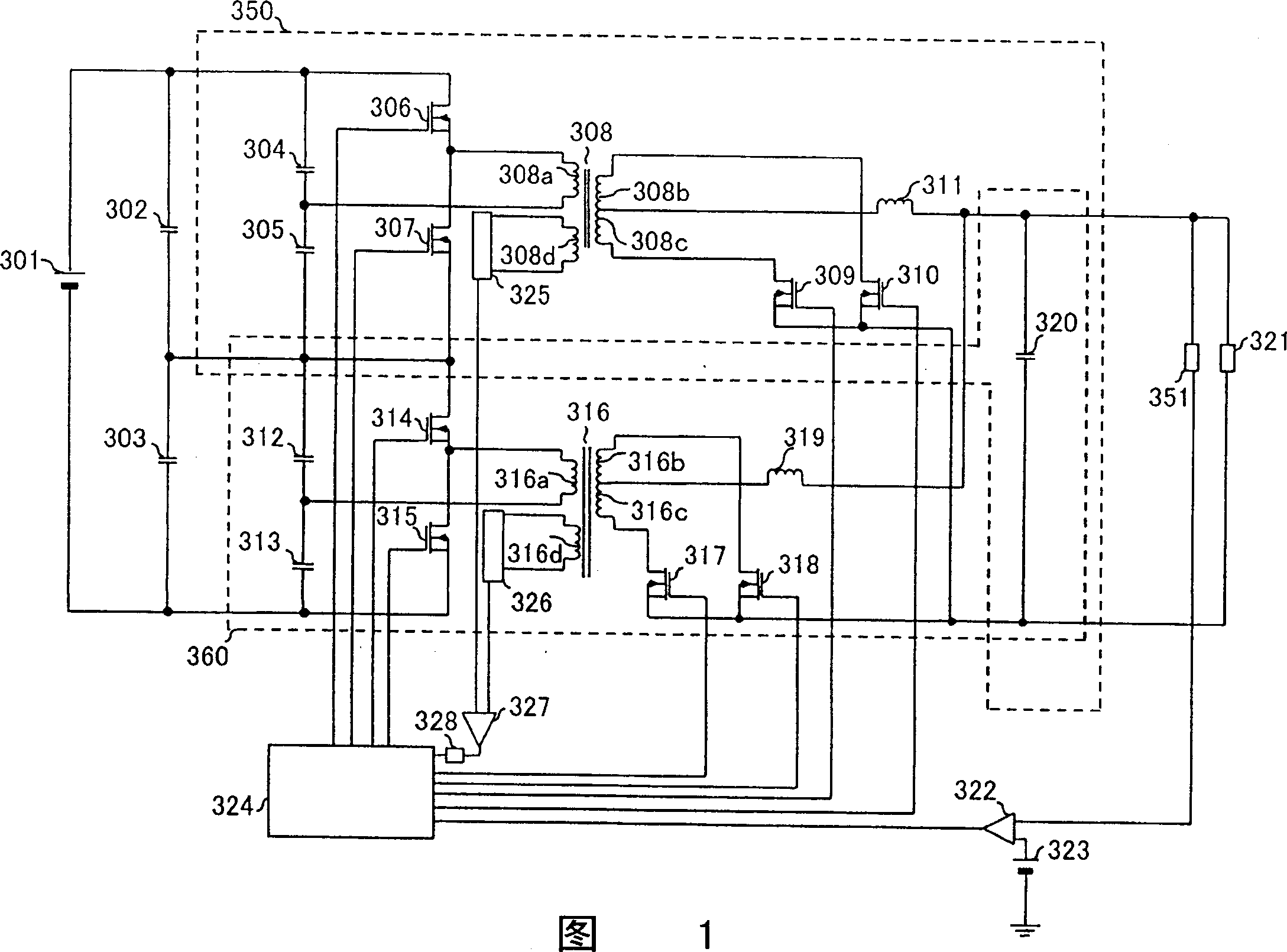
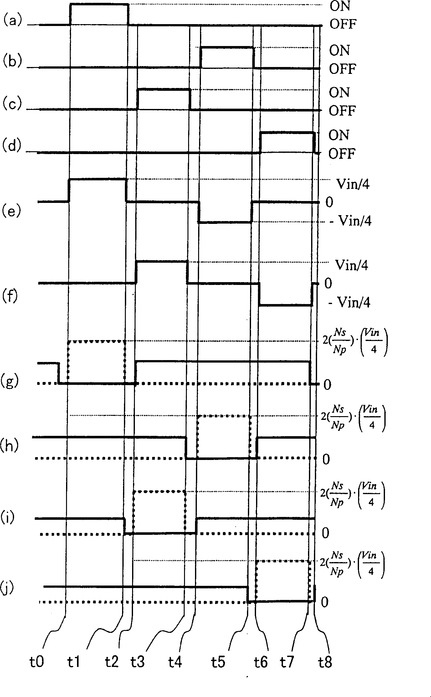
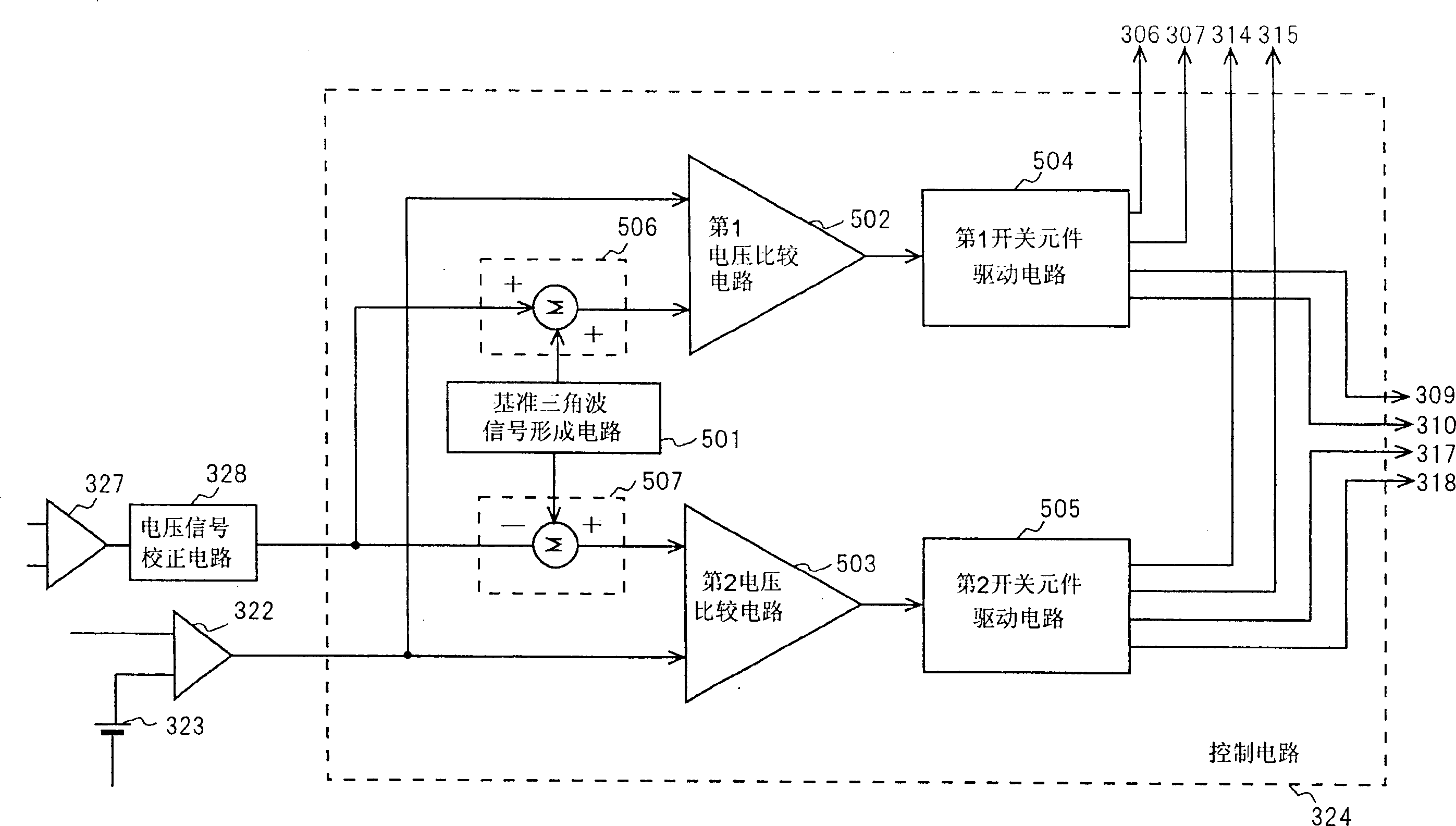
[0056] Fig. 1 is a circuit diagram showing the configuration of a switching power supply device according to Embodiment 1 of the present invention. The switching power supply device according to Embodiment 1 shown in FIG. 1 is composed of two sets of half-bridge DC-DC converters (hereinafter simply referred to as half-bridge converters) 350 and 360, whose input sides are connected in series and whose output sides are connected in parallel. That is, in the switching power supply device of Embodiment 1, the two capacitors 302 and 303 are connected in series, the voltage of the DC power supply 301 is divided, and the divided voltage is applied to the first half-bridge converter 350 and the second half-bridge converter 350 . half-bridge converter 360 on. The capacitors 302 and 303 may b...


PUM


Abstract

A switching power supply wherein output voltage error detecting means detects the output voltage of DC-DC converters and generates an error signal, input voltage deviation detecting means detects voltages corresponding to the input voltages of the DC-DC converters to generate a deviation signal, and control means receives the error signal of the output voltage error detecting means and the deviation signal of the input voltage deviation detecting means and controls the driving of the DC-DC converters.

Description

technical field [0001] The invention relates to a DC stable power supply device for industrial and civil electronic equipment. In particular, the present invention relates to improving the control stability of DC-DC converters of switching power supply devices. Background technique [0002] In recent years, with regard to switching power supply devices, along with the reduction in price, miniaturization, high performance, and energy saving of electronic equipment, there has been an urgent demand for a power supply device with high output stability, small size, and high efficiency. In particular, for power supplies for powering semiconductor devices, power supply devices capable of supplying large currents at lower voltages and with higher stability are increasingly required as semiconductors become more highly integrated. [0003] 11A, 11B, 11C, and 11D are circuit diagrams showing various configuration examples of a DC-DC converter in a conventional switching power supply ...

Claims


Application Information

Patent Timeline
Patent Type & Authority Applications(China)
IPC IPC(8): H02M3/28H02M3/335
CPCH02M2001/0074Y02B70/1475H02M2001/0022H02M3/285H02M3/33592H02M1/0022H02M1/0074Y02B70/10
Inventor 松尾光洋吉田幸司
Owner PANASONIC CORP
Why Eureka
Try Eureka