
Color sorting machine

A color and machine technology, applied in the field of color sorting machines, can solve problems such as inability to separate

Inactive Publication Date: 2004-08-25
AMECS
View PDF0 Cites 18 Cited by
  • Summary
  • Abstract
  • Description
  • Claims
  • Application Information

AI Technical Summary

Problems solved by technology

Since the ejector nozzle is circular, it will spray widely, therefore, it is not possible to precisely separate the desired items from the defective ones

Method used


Image

  • Color sorting machine
  • Color sorting machine
  • Color sorting machine

Examples


Embodiment Construction

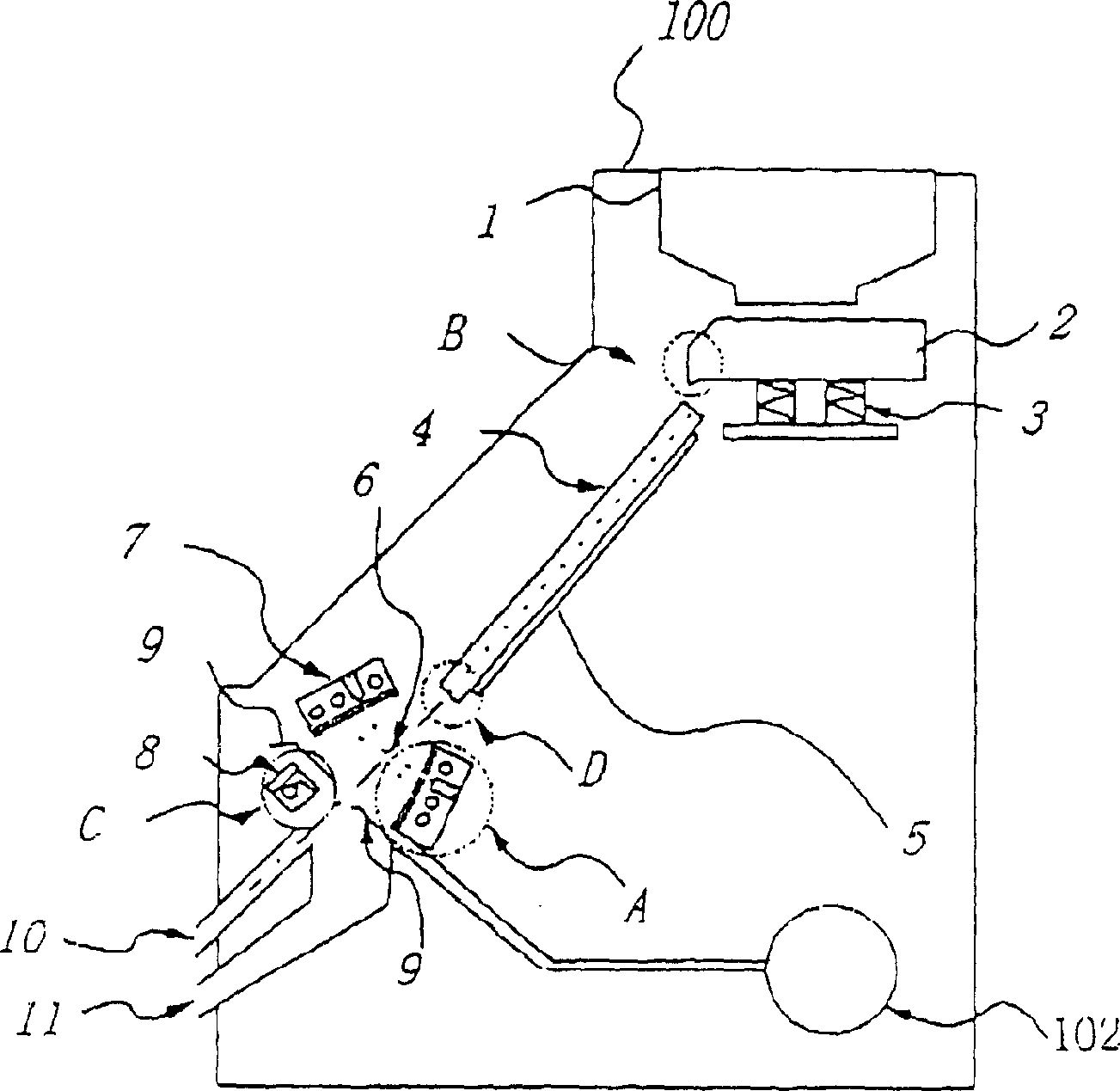
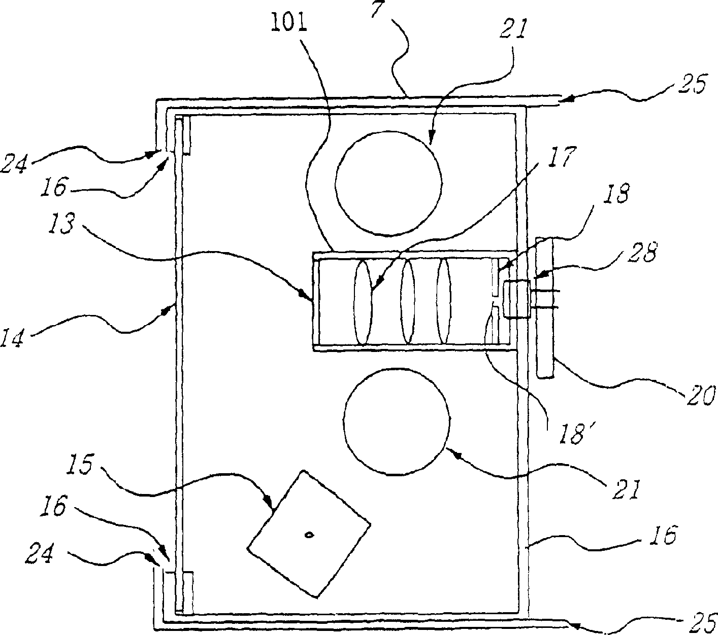
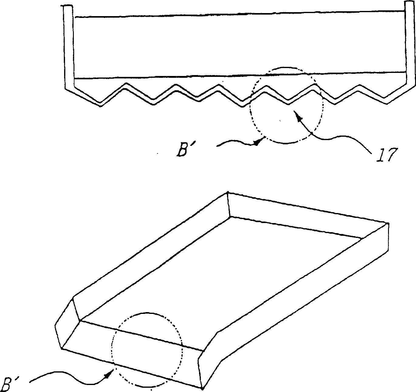
[0014] figure 1 It is a sectional view of the color sorting machine of the present invention. refer to figure 1 , the color sorting machine 100 includes a hopper 1 located on the upper part for containing granular materials and a feeder 2 located below the hopper. Such as image 3 As shown, the feeder 2 has such a structure that its front end is inclined, thereby allowing the granular material to run down to a descending slope 4 easily and evenly, and a V-shaped or U-shaped guide groove 17 is also formed. (see image 3 the upper part of the). The guide grooves 17 coincide with the individual channels of the down ramp 4 , allowing the granular material to enter the down ramp 4 evenly and precisely. A vibrating part 3 is located below the feeder 2 . Below the feeder 2, several channels are formed, each channel comprising a descending ramp 4 with a U-shaped or V-shaped bottom. Under certain air conditions, such as a high percentage of humidity, the descending ramp 4 can be...


PUM


Abstract

The present invention discloses a color sorting machine. Said machine includes a hopper which is positioned in upper most portion and through which the granular material can be charged; a feeder which is positioned under the hopper and is formed into a guide recessed groove; a downward slope connected with vibrator positioned in rear portion; an U-shaped slope which can make the detected material uniformly pass through the guide recessed groove and slide; an air spraying system for cleaning transparent plate of detection portion; and a slot-like sprayer nozzle, said nozzle can make the detected material be accurately and effectively blown out by means of air. Said color sorting machine has high selective accuracy, stable production efficiency and high quality.

Description

technical field [0001] The present invention relates to a color sorting machine. Specifically, the present invention relates to a color sorting machine comprising: a feeder formed with a guide groove; a descending ramp with an arcuate U-shaped channel, and A vibrator (hitter) is attached to the head; an air shower system, which can clean the transparent plate of the detector; and an ejector, which has an air nozzle-shaped slot that can blow out defective products. Background technique [0002] Recently, there are many color sorting machines that can separate a particular granular material from other granular materials, generally based on color. These machines are used for color sorting of various granular materials such as cereals, plastic pellets, tablets etc. [0003] However, there are some problems with such traditional color sorting machines. That is, the particulate material does not pass uniformly from the feeder into a descending ramp because operating conditions ...

Claims


Application Information

Patent Timeline
Patent Type & Authority Applications(China)
IPC IPC(8): B07B13/00
Inventor 申锡虎
Owner AMECS
Learn More