Milling cutter and cutting insert therefor

A technology for cutting inserts and milling cutters, used in milling cutters, forming cutters, linear broaches, etc.

Inactive Publication Date: 2004-08-25
ISCAR LTD
View PDF2 Cites 5 Cited by
  • Summary
  • Abstract
  • Description
  • Claims
  • Application Information

AI Technical Summary

Problems solved by technology

If the patent Figure 8 As shown, the milling cutter is only suitable for machining the side of the cam of the camshaft

Method used


Image

  • Milling cutter and cutting insert therefor
  • Milling cutter and cutting insert therefor
  • Milling cutter and cutting insert therefor

Examples


Embodiment Construction

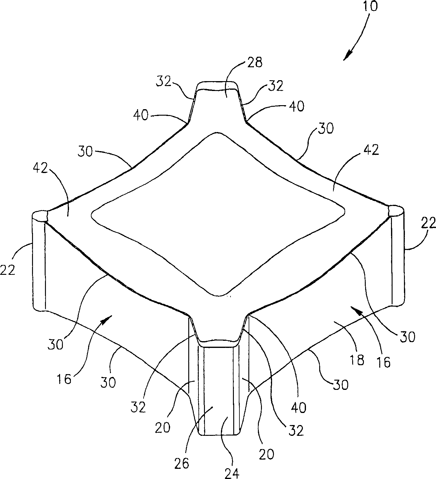
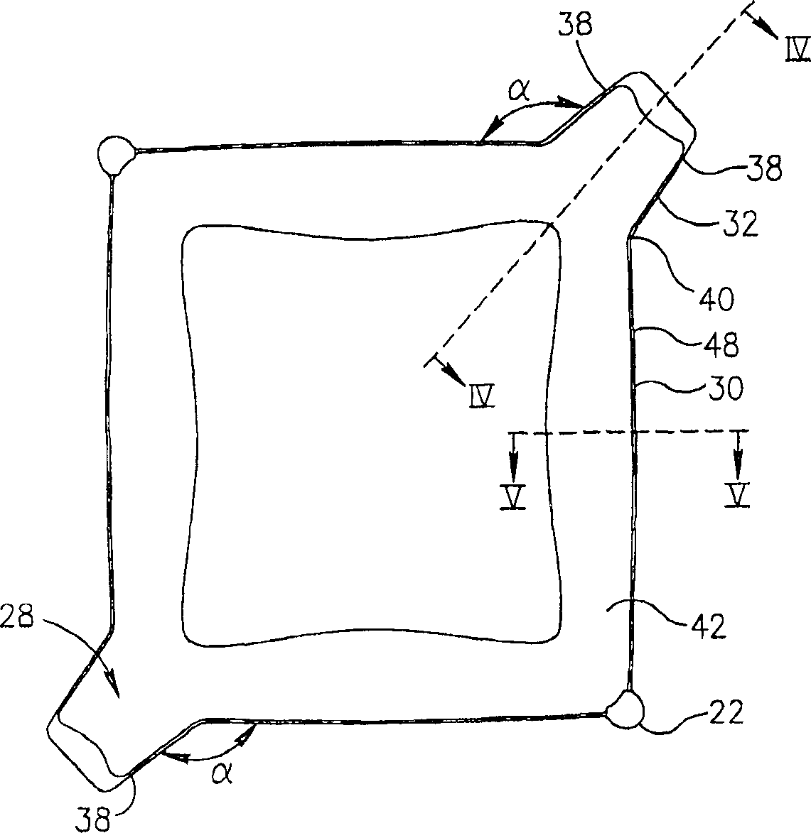
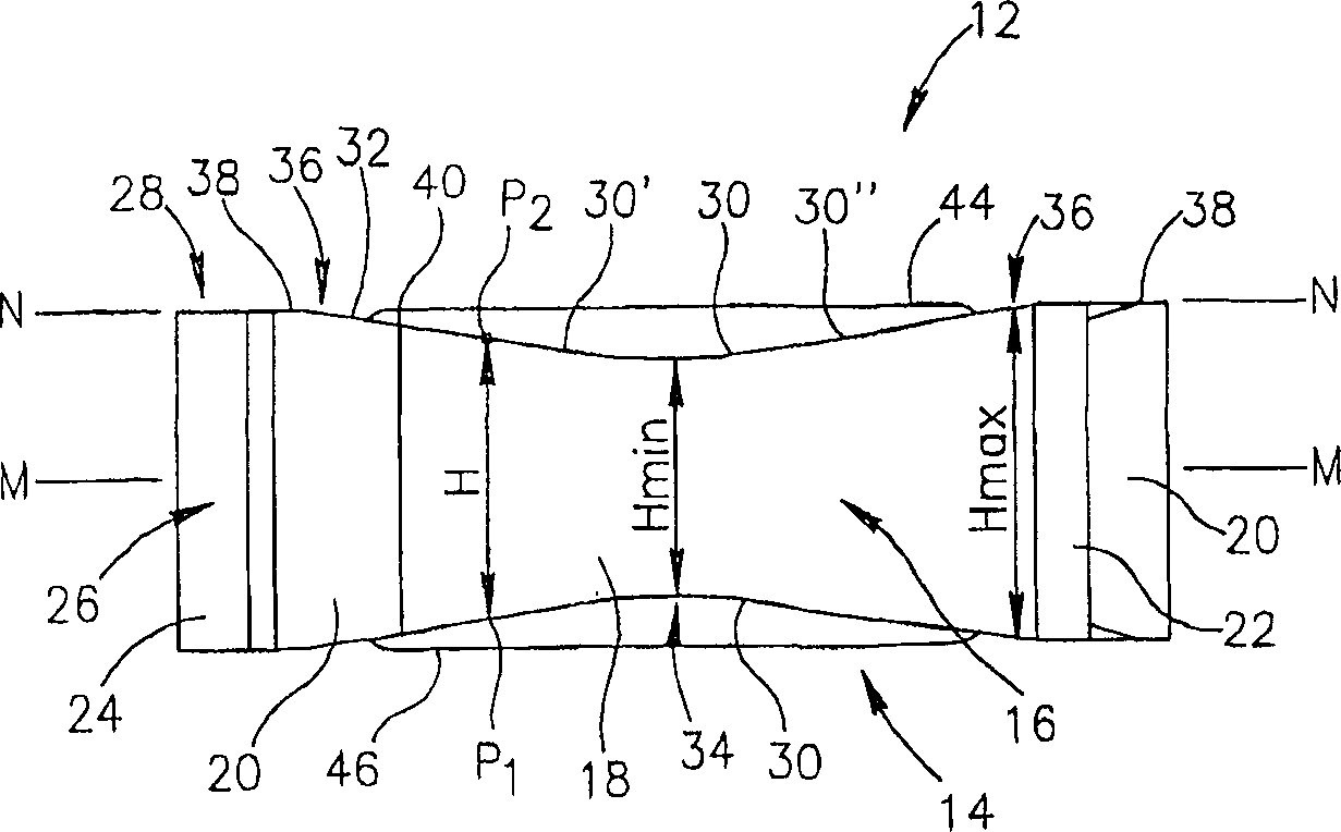
[0043] see Figure 1~3 . The cutting insert 10 of the present invention has a top surface 12 and a bottom surface 14 that are generally square. The cutting insert can be pressed and sintered, or it can be injection molded. Four identical general sides 16 extend between the top surface 12 and the bottom surface 14 . The sides 16 are identical in design, but one or more sides may differ slightly from the desired design due to the manufacturing process. For example, as is known, cutting inserts shrink during sintering, which shrinkage may not be uniform. Therefore, it is possible to obtain identical cutting inserts taking into account manufacturing tolerances. Each side 16 includes a major side 18 connected to an adjacent minor side 20 . Adjacent main sides 18 meet at two diametrically opposite corner edges 22 .

[0044] Adjacent secondary sides 20 meet at a medial side 24 . The two adjacent secondary flanks 20 and the intermediate flank 24 form a peripheral flank 26 of a ...


PUM


Abstract

An indexable cutting insert for use in a milling cutter. The cutting insert having four identical side surfaces extending between generally square shaped top and bottom surfaces with two diametrically opposite protuberances extending away from each other in a top or bottom view of the cutting insert. The cutting insert has eight identical major and minor cutting edges. The milling cutter having the general form of a circular disk with a plurality of the cutting inserts releasably mounted in insert pockets angularly around the periphery of the cutter. The cutting inserts are arranged to produce a profile on a workpiece having a central straight section and two beveled sections on either side of the central straight section.

Description

technical field [0001] The present invention relates generally to milling cutters and cutting inserts for machining metal workpieces and in particular for machining cams of camshafts. Background technique [0002] This type of milling cutter is shown in JP2000052131. The milling cutter disclosed in this patent comprises two sets of tangential cutting inserts arranged in pairs and staggered on the periphery. The two cutting inserts of a given pair at least partially overlap when superimposed. If the patent Figure 8 As shown, the milling cutter is only suitable for machining the side of the cam of the camshaft. [0003] Another milling cutter that is used to process the cam of the camshaft sees JP11138325. The milling cutter can not only machine the side of the cam, but also chamfer the edge of the side. The milling cutter disclosed in this patent also includes sets of cutting inserts arranged in a circumferentially staggered arrangement. The first pair of cutting insert...

Claims


Application Information

Patent Timeline
Patent Type & Authority Applications(China)
IPC IPC(8): B23C3/08B23C5/08B23C5/12B23C5/20
CPCB23C5/207B23C5/08B23C3/08Y10T407/235Y10T407/1614Y10T83/9319Y10T83/9372Y10T83/9464B23C5/202B23C5/20
Inventor A·萨特兰D·尤里亚尼特斯基
Owner ISCAR LTD
Why Eureka
Try Eureka