Liquid drop ejector and method for detecting/judging abnormality of head

A droplet nozzle and droplet technology, applied in planting methods, agricultural machinery and implements, printing, etc., can solve the problems of expensive detectors, lowering, inability to choose recovery processing, etc., to prevent throughput from being reduced or deteriorated, and reduce uselessness. The effect of ink discharge

Active Publication Date: 2004-09-01
SEIKO EPSON CORP
View PDF1 Cites 40 Cited by
  • Summary
  • Abstract
  • Description
  • Claims
  • Application Information

AI Technical Summary

Problems solved by technology

Such detectors are generally expensive, and as a result there is a problem of increasing the manufacturing cost of inkjet printers
In addition, the reliability of the detector may also become a problem due to the contamination of the light source output part and the detection part of the optical sensor due to mis-ejection of ink from the nozzle and paper powder such as printing paper.
[0005] In the above-mentioned optical leak detection method, the leak of the nozzle can be detected, i.e., the ejection of the ink droplet is abnormal (not ejected), but the cause of the leak (abnormal ejection) cannot be judged (determined) based on the detection result, Cannot choose to perform the appropriate recovery process corresponding to the cause of the leak point
Therefore, in the missing dot detection method of the prior art, the sequence recovery process is performed regardless of the cause of the missing dots. For example, in the wiping process, regardless of whether it is a recoverable state, by sucking ink from the inkjet head with a pump, etc., the discharge rate is increased. Ink (Useless ink), due to inability to perform proper recovery processing, will reduce or deteriorate the throughput of the inkjet printer (droplet ejection device) by performing multiple recovery processes
[0006] However, generally, a droplet ejection device (inkjet printhead) has a plurality of nozzles and corresponding actuators, but in such a droplet ejection device with a plurality of nozzles, it is difficult to reduce or deteriorate the throughput of the device. In the case of liquid droplet (ink) ejection abnormality (non-ejection) is detected, that is, dot omission during printing (recording) operation is detected

Method used


Image

  • Liquid drop ejector and method for detecting/judging abnormality of head
  • Liquid drop ejector and method for detecting/judging abnormality of head
  • Liquid drop ejector and method for detecting/judging abnormality of head

Examples


no. 1 approach

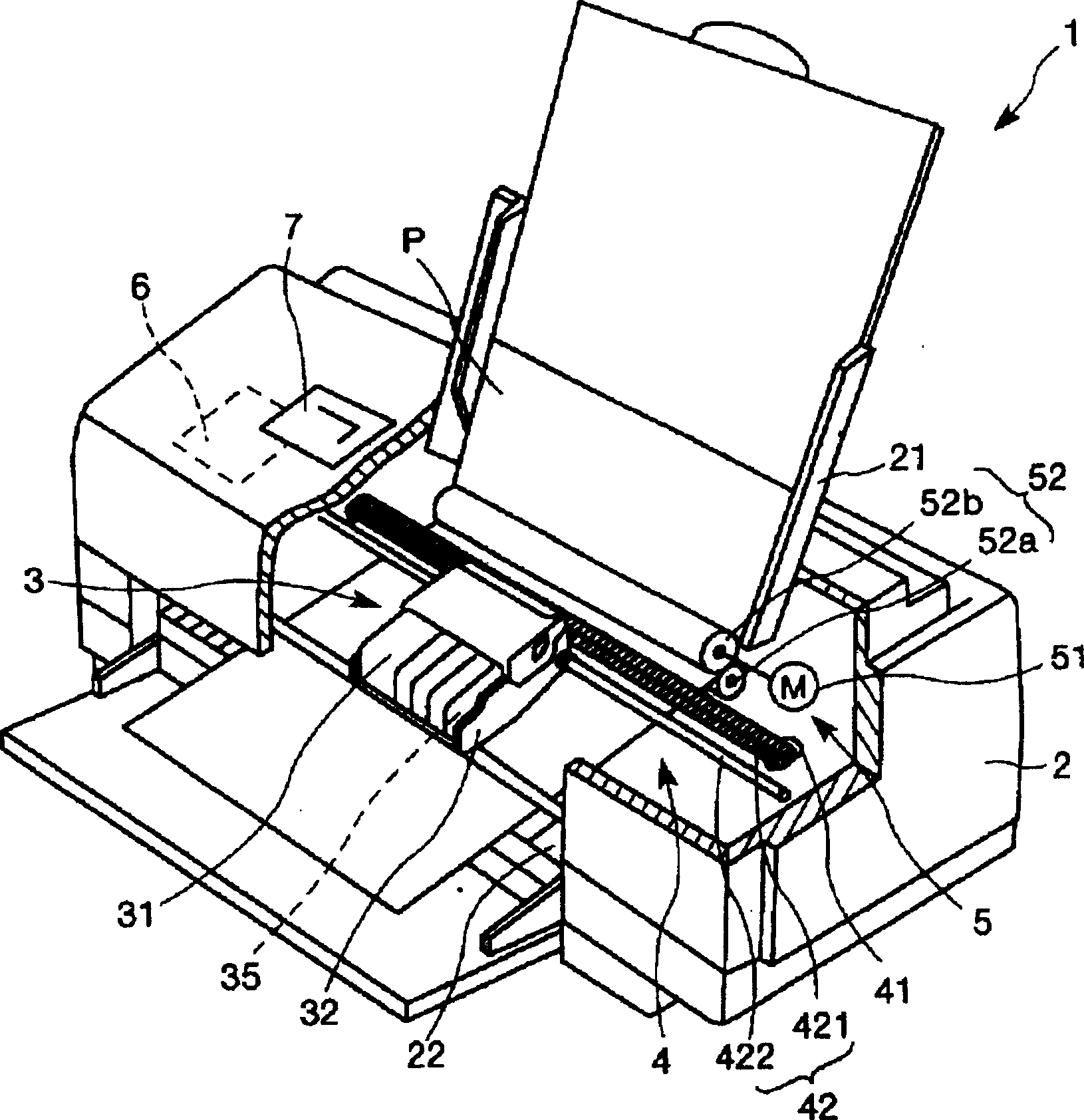
[0134] figure 1 It is a schematic diagram showing the configuration of an inkjet printer 1 which is one type of the droplet ejection device according to the first embodiment of the present invention. In the description below, figure 1 The upper side is called the upper part, and the lower side is called the lower part. First, the configuration of the inkjet printer 1 will be described.

[0135] figure 1 The inkjet printer 1 shown includes a device main body 2, a tray 21 for recording paper P is designed at the upper rear, a paper outlet 22 for sending recording paper P is designed at the lower front, and an operation panel 7 is designed on the upper surface.

[0136] The operation panel 7 is composed of, for example, a liquid crystal display, an organic EL display, LED lights, etc., and includes a display portion (not shown) that displays error messages and the like, and an operation portion (not shown) composed of various switches and the like. The display portion of the ...

no. 2 approach

[0357] Next, other structural examples of the inkjet head of the present invention will be described. Figure 44 ~ Figure 47 Each is a schematic cross-sectional view showing another structural example of the inkjet head (head unit). The following description will be made based on these figures, but the description will focus on the differences from the above-mentioned embodiment, and the description of the same items will be omitted.

[0358] Figure 44 In the illustrated inkjet head 100A, the vibration plate 212 is vibrated by driving the piezoelectric element 200 , and the ink (liquid) in the chamber 208 is ejected from the nozzles 203 . On the nozzle plate 202 made of stainless steel forming the nozzle (hole) 203, a metal plate 204 made of stainless steel is bonded via an adhesive film 205, and a metal plate 204 made of stainless steel is also bonded thereon through an adhesive film 205. Further, the communication port forming plate 206 and the chamber plate 207 are bonde...

no. 3 approach

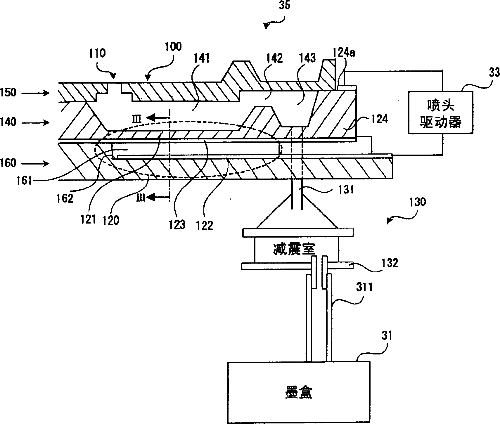
[0374] Next, another structural example of the inkjet head of the present invention will be described. Figure 48 It is a perspective view showing the structure of the head unit 35 of this embodiment, Figure 49 yes Figure 48 A sectional view of the head unit 35 (inkjet head 100H) is shown. The following description will be made based on these figures, but the description will focus on the differences from the above-mentioned embodiment, and the description of the same matters will be omitted.

[0375] Figure 48 and Figure 49 The shown head unit 35 (inkjet head 100H) is based on a so-called film boiling inkjet method (thermal jet method), and a support plate 410, a substrate 420, an outer wall 430, a partition plate 431, and a top plate 440 Figure 48 and Figure 49 Glue in order from the bottom side.

[0376] The base plate 420 and the top plate 440 are provided at predetermined intervals via the outer wall 430 and a plurality of (six in the example in the drawing) p...


PUM


Abstract

A droplet ejection apparatus of the invention includes: a plurality of droplet ejection heads (100); ejection failure detecting means (10) for detecting an ejection failure of droplets through nozzles; and recovery means (24) for performing recovery processing to eliminate a cause of the ejection failure of the droplets, wherein in a case where detection by the ejection failure detecting means (10) is performed for all of the nozzles and the presence of a failing nozzle in which an ejection failure is occurring is detected, recovery processing depending on the cause of the ejection failure is performed by the recovery means (24) at least for the failing nozzle, after which detection by the ejection failure detecting means (10) is performed again by forcing the failing nozzle alone to perform a droplet ejection operation.

Description

field of invention [0001] The present invention relates to a liquid drop ejecting device and a method for recovering abnormal ejection. Background technique [0002] An inkjet printer, which is one of the droplet ejection devices, ejects ink droplets (droplets) from a plurality of nozzles to form an image on predetermined paper. The print head (inkjet head) of an inkjet printer is equipped with multiple nozzles, but due to reasons such as increased ink viscosity, air bubbles, dust and paper dust adhesion, sometimes several nozzles are blocked and ink droplets cannot be ejected. When the nozzles are clogged, missing dots are generated in the printed image, which causes image quality to deteriorate. [0003] In the past, as a method for detecting such an abnormality in the ejection of ink droplets (hereinafter also referred to as "missing dots"), in Japanese Patent Laid-Open No. 8-309963, a method is disclosed. A state in which ink droplets are not ejected from the nozzles o...

Claims


Application Information

Patent Timeline
Patent Type & Authority Applications(China)
IPC IPC(8): B41J2/14B41J2/165
CPCB41J2/04581B41J2/04578B41J2/0458B41J2/14314B41J2002/14411B41J2/0451A01B1/08A01C5/02A01C11/04
Inventor 新川修坂上裕介
Owner SEIKO EPSON CORP
Why Eureka
Try Eureka