Universal wheel

A technology of universal wheels and rims, which is applied in the direction of casters, wheels, transportation and packaging, etc. It can solve the problems of complex structure and process of half hubs, the inability to install other parts on wheels, and affect the service life of wheel frames, etc., so as to achieve good connection , saving structure rotation space, the effect of reasonable structure

Inactive Publication Date: 2004-09-01
黄善钧 +1
View PDF2 Cites 13 Cited by
  • Summary
  • Abstract
  • Description
  • Claims
  • Application Information

AI Technical Summary

Problems solved by technology

[0002] Traditional swivel casters are driven by external force, and its wheels must be turned to be consistent with the direction of the external force before it can be dragged by the external force to move along the direction of the external force. When the external force changes the direction of motion, the traditional swivel caster needs to be adjusted for a while. The process of the wheel direction, in this way, there is often a swing phenomenon during use, and the use is not flexible, and the direction of the traditional swivel caster is offset by a certain distance from the center of the wheel, which makes the wheel frame produce a large eccentric moment, which affects the use of the wheel frame service life, and the installation space of traditional swivel casters must leave space for the wheels to rotate around the vertical axis of the wheel frame
[0003] The inventor proposed a utility model, an invention patent and a PCT application in December 2002, application numbers: 02291781.0, 02130670.2 and PCT / CN02 / 00880 three "a new type of universal wheel" with the same structure, and its embodiment is The Y-shaped bracket is installed on the small drum-shaped roller, but there are shortcomings in this Y-shaped bracket. This bracket will pass between two large drum-shaped rollers and be fixed at the center of the half hub groove, so that The structure of the wheel will affect that other parts, such as rolling bearings, cannot be installed in the center of the wheel. At the connection between the large and small drum-shaped rollers, the end faces of the large drum-shaped rollers have a large gap, which is easily invaded by sand and soil, which affects the rotation of the large and small rollers. , the structure and process of the half-hubs on both sides are complicated, which increases the processing cost accordingly
[0004] According to Chinese patents and other relevant data retrieval, except for my invention, there is no report of a new type of universal wheel in which a single row of rollers can be pushed to move in any direction with an external force without turning the direction of the wheel when in use.

Method used


Image

  • Universal wheel
  • Universal wheel
  • Universal wheel

Examples


Embodiment 1

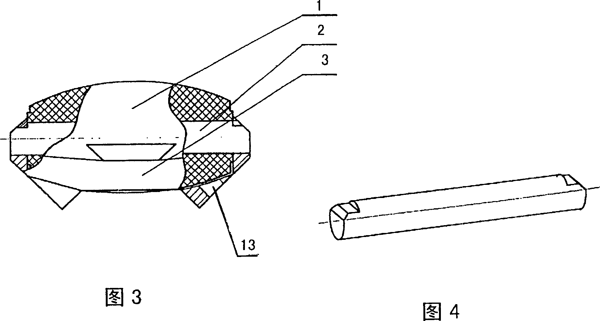
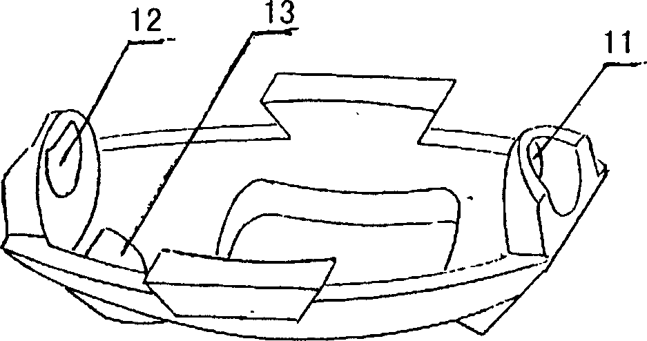
[0019] Please refer to Fig. 1~8, Fig. 1 is the implementation plan figure of the novel universal wheel that four pairs of big and small drum-shaped rollers form. The two ends axle noses of long mandrel 2 are made half moon shape, see Fig. 4. Pass the long mandrel 2 through the shaft hole 11 on the right support of the bat-shaped support 3, then through the center hole of the small waist drum-shaped roller 1, and then insert it into the half-moon-shaped shaft hole 12 on the left support of the bat-shaped support 3 middle. See Figure 5 And Fig. 3, the small waist drum shaped roller 1 has just been installed on the bat support 3 central positions like this, and can rotate freely. Now, the half-moon shaft head at the right end of the long mandrel 2 is riveted on the right side support of the bat-shaped support 3, and a half-moon shaft hole 13 is respectively arranged at the left and right lower parts of the bat-shaped support 3. See Figure 5 As shown in Fig. 3, the drum-shaped...


PUM


Abstract

The invention relates to the structure and shape of a universal wheel, disclosing a new universal wheel, composed of big and small waist drum rollers, batwing bracket, long and short mandrels, side cover plate, bearing, sleeve, central shaft, wheel frame and so on. Its character: the two rollers and the two mandrels fixed on the batwing bracket compose the wheel edge, the batwing bracket is linked with the side cover plate, and the bearing, the central shaft and the wheel frame are installed in the center of the side cover plate, thus composing it. It uses the two rollers to compose double-freedom mechanism, thus able to be pushed in an arbitrary direction to move without rotating the direction of the wheel when used, saving the rotary space. In addition, it has not only better stopping property to prevent the sand from intruding into the inner cavity of the rollers, but also has advantages of reasonable structure, good technique, etc.

Description

technical field [0001] The invention relates to the structure and shape of a universal wheel, in particular to the structure and shape of a new type of universal wheel that can move in any direction on flat ground with external force without turning the direction of the wheel. Background technique [0002] Traditional swivel casters are driven by external force, and its wheels must be turned to be consistent with the direction of the external force before it can be dragged by the external force to move along the direction of the external force. When the external force changes the direction of motion, the traditional swivel caster needs to be adjusted for a while. The process of the wheel direction, in this way, there is often a swing phenomenon during use, and the use is not flexible, and the direction of the traditional swivel caster is offset by a certain distance from the center of the wheel, which makes the wheel frame produce a large eccentric moment, which affects the u...

Claims


Application Information

Patent Timeline
Patent Type & Authority Applications(China)
IPC IPC(8): B60B33/00
Inventor 黄善钧黄长江
Owner 黄善钧
Why Eureka
Try Eureka