Method for cooling turbomachine and turbomachine for applicating the same method

A technology for cooling turbines and turbines, which is applied to the cooling of engines, gas turbine devices, machines/engines, etc., and can solve the problems of stopping the cooling effect and increasing the cost of separate pipelines, etc.

CN1526928AInactive Publication Date: 2004-09-08SIEMENS AG
0 Cites 3 Cited by

Patent Information

Authority / Receiving Office
CN · China
Patent Type
Applications(China)
Current Assignee / Owner
Publication Date
2004-09-08
Estimated Expiration
Not applicable · inactive patent

Smart Images

  • Figure 1
    Figure 1
  • Figure 2
    Figure 2
Patent Text Reader

Abstract

A turbo-engine (TE) (1) has a fresh steam supply (FSS) (9), an admission area (17), a casing (2) and a waste steam area (7). During operation, a flowing medium flows through the turbo-engine and leaves in the waste steam area. Cooled by a heat-exchanger (8) prior to entry into the TE, part of the flowing medium from the FSS is directed towards a thrust compensating piston (19). An Independent claim is also included for a turbo-engine with a fresh steam supply with a direct-flow medium.
Need to check novelty before this filing date? Find Prior Art

Description

technical field

[0001] The invention relates to a method for cooling thermally loaded regions in a turbine having a live steam feed line, an inflow region, a housing and a waste steam region, as well as a turbine for carrying out the method, wherein , during operating mode a flow medium flows through the turbine and exits in the exhaust steam region. Background technique

[0002] In turbine construction, especially in steam turbine construction, it is necessary to cool areas subjected to high thermal loads with steam whose temperature is lower than that of the live steam at the live steam pressure. The live vapor pressure is the pressure of a flow medium which can enter the inflow region of the turbine. The live steam temperature corresponds to the temperature that a flow medium has at the inlet to the turbine.

[0003] Cold steam with the above-mentioned characteristic values ​​of temperature and pressure cannot be provided by the turbine itself in current turbines. [0...

Examples

Embodiment Construction

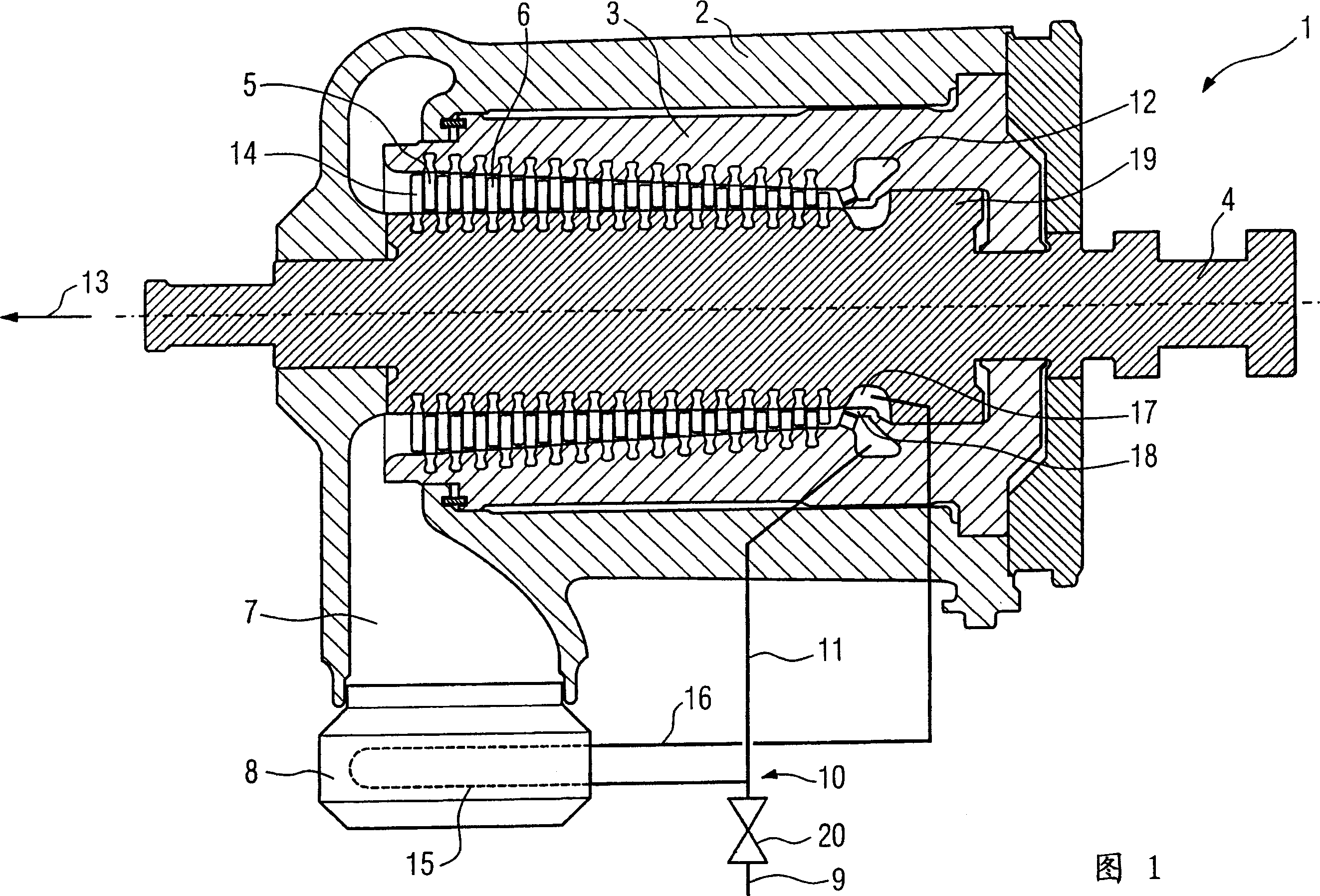
[0019] FIG. 1 shows a turbine 1 . The turbine 1 has a housing 2 . An inner housing 3 is arranged such that a shaft 4 can rotate in said inner housing 3 . The inner housing 3 has guide vanes 5 . The shaft 4 then has rotor blades 6 . A heat exchanger 8 is installed in the waste steam region 7 . The heat exchanger 8 also does not necessarily have to be arranged in the exhaust steam region of the turbine 1 .

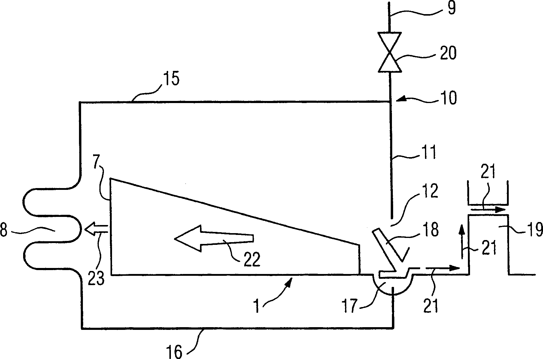
[0020] The live steam is fed from a steam boiler (not shown) via the live steam supply line 9 to the turbine 1 . At the split point 10 a part of the live steam is led to the heat exchanger 8 . The temperature of the fresh steam can reach 565° C. and the pressure can reach 250 bar before being diverted at the split point 10. The remaining live steam, ie the live steam not directed to the heat exchanger 8 , enters the turbine 1 via a line 11 . At this point, the live steam reaches the live steam inflow region 12 , and the flow medium flows from the live steam inflow reg...