

Sheet separating supplier and offset printer
A technology for supplying devices and sheets, applied in printing presses, general parts of printing machinery, printing, etc., to achieve the effects of simplifying control actions, simplifying device structure, and preventing overlapping conveyance
- Summary
- Abstract
- Description
- Claims
- Application Information
AI Technical Summary
Problems solved by technology
Method used
Image

Examples
Embodiment Construction
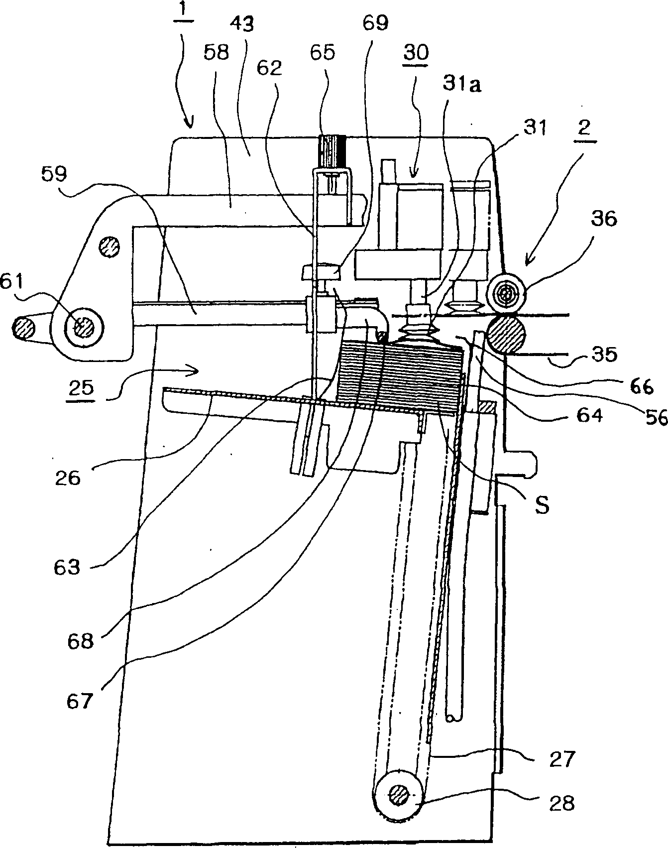
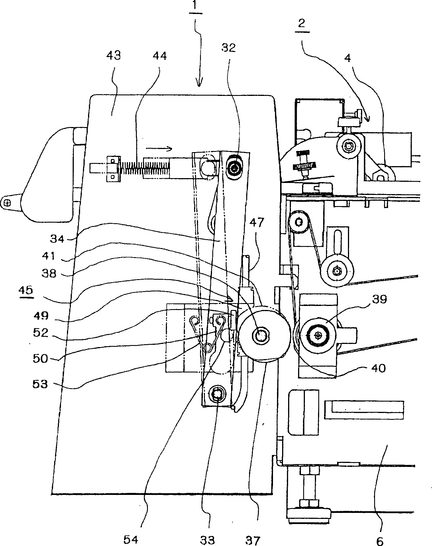
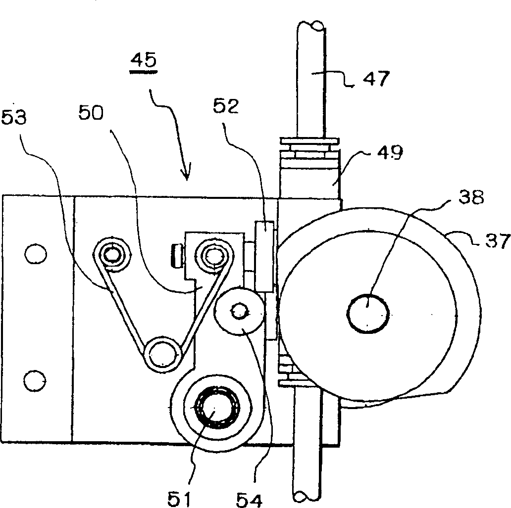
[0036] First, combined with Figure 8~ Figure 10 The structure of an offset printing machine will be explained. In this embodiment, the type of printing unit is an offset printing machine that supplies water and ink separately.
[0037] In Figure 9 and Figure 10 Among them, the sheet separating and supplying device 1 separates sheets (such as business cards, cards, and envelopes, plastics, etc.) S stacked in the storage section one by one from the uppermost side, and supplies them. The sheet conveying device 2 feeds the separated sheet S to the printing unit 3 at a predetermined time. The sheet conveying device is provided with conveying claws (not shown) that abut against the rear end of the sheet S and feed the sheet into the printing section, and several pressure rollers 4 arranged in series along the conveying direction of the sheet S . The printing unit 3 can perform monochrome printing on the sheet S, and of course can also perform color printing. Using an image sc...
PUM
 Abstract
Description
Claims
Application Information