
Counter weight mounting structure for building machinery

A technology for installing structures and construction machinery, which is used in construction, cranes, earthmovers/shovels, etc., and can solve problems such as reduced sound insulation performance, separation or damage of sound insulation materials, etc.

Inactive Publication Date: 2004-10-06
KOBELCO CONSTR MASCH CO LTD
View PDF1 Cites 16 Cited by
  • Summary
  • Abstract
  • Description
  • Claims
  • Application Information

AI Technical Summary

Problems solved by technology

[0006] When using a crane for loading / unloading work involving lifting / lowering of counterweights, there has been a problem that the soundproofing performance is lowered because the soundproofing material may be separated or damaged

Method used


Image

  • Counter weight mounting structure for building machinery
  • Counter weight mounting structure for building machinery
  • Counter weight mounting structure for building machinery

Examples


Embodiment Construction

[0019] A counterweight mounting structure for a construction machine according to the present invention will be described based on FIGS. 1 to 8 related to the following embodiments.

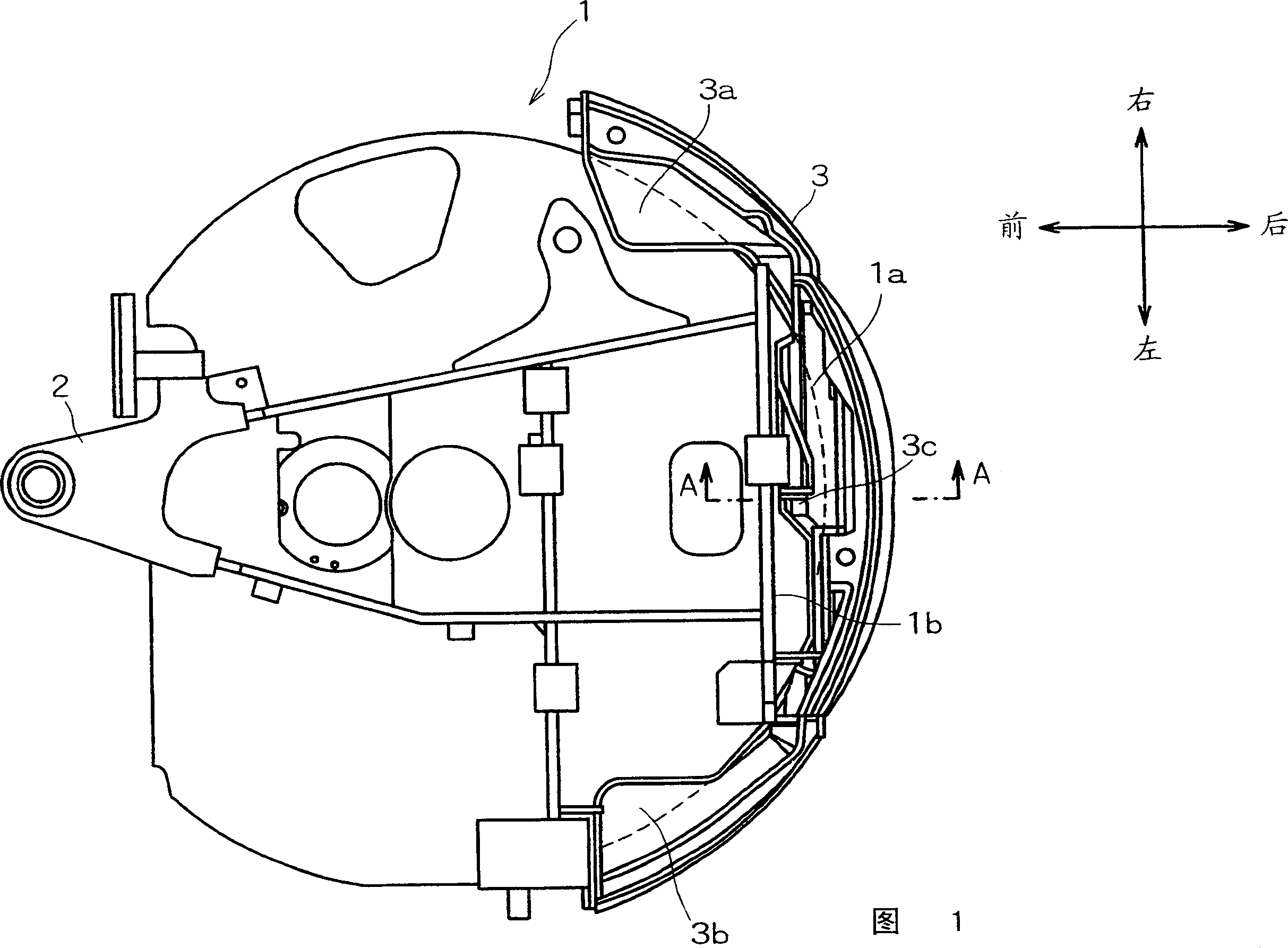
[0020] Hereinafter, a hydraulic excavator will be described as an example of a construction machine. The hydraulic excavator is configured by rotatably attaching an upper rotating body to a lower traveling body. A working device consisting of a bucket, an arm, and a boom is pivotally supported on the front of the upper rotating body, and a counterweight is mounted on its rear or tail. Fig. 1 is a plan view showing the arrangement of a counterweight and a rotating frame to which the present invention is applied.

[0021] The swivel frame 1 shown in Figure 1 is used for an excavator with a short rear swivel (space) radius, when the overhanging tail of the tracked vehicle has zero swivel, or is capable of swiveling in most cases of use at the job site , not protruding from the rear of the tracked ...


PUM


Abstract

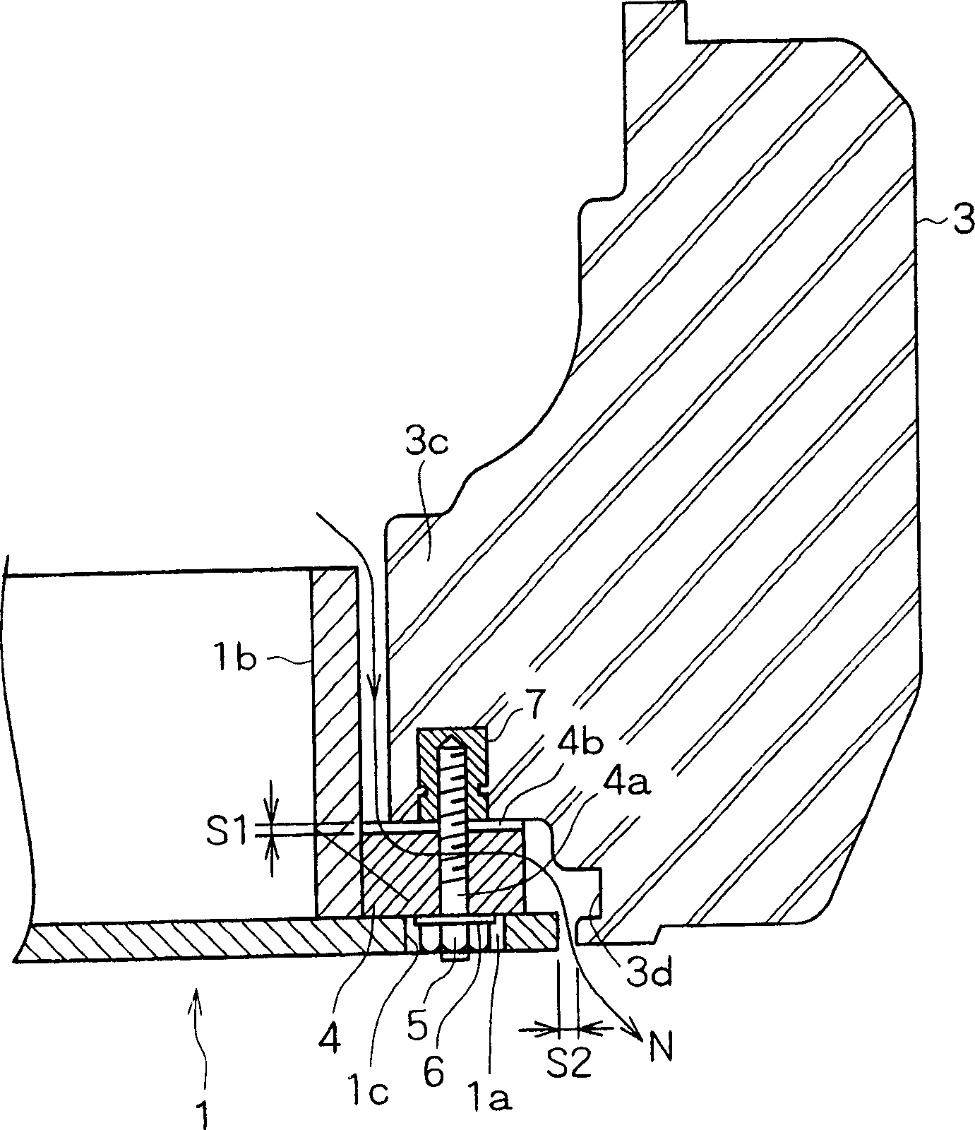
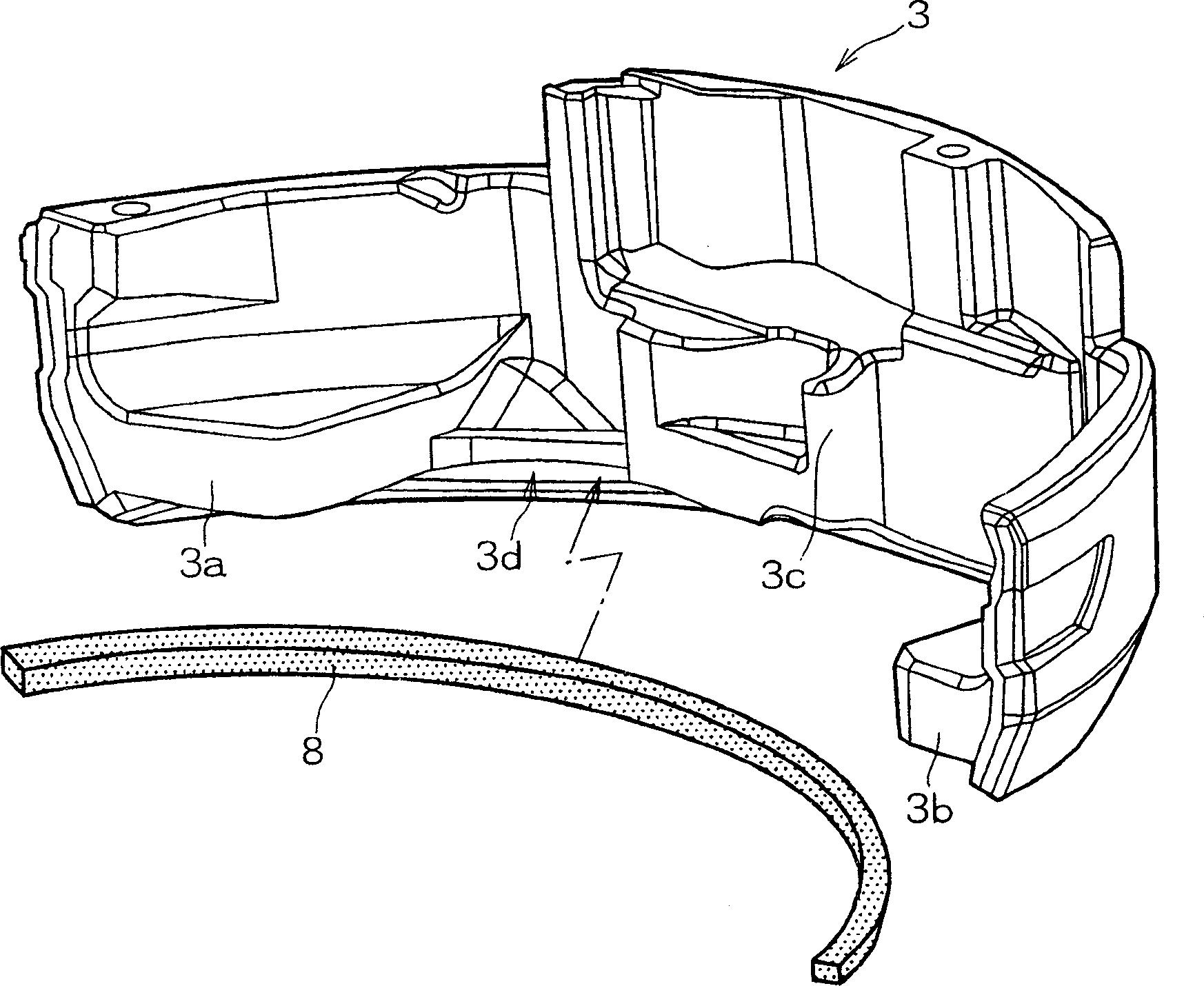
A counterweight mounting structure for construction machine to which a counterweight is connected through a gap to an exterior constituting an upper rotating body is constituted such that a recessed groove is provided on an end on a connection side of the counterweight, an elastic soundproof material is installed in the recessed groove, and the soundproof material protruding from the recessed groove is brought in contact with, and pressed against an end on the connection side of the exterior when the counterweight is mounted. As a result, there is provided the counterweight mounting structure whose soundproof capability does not decrease even after the counterweight is mounted / dismounted.

Description

technical field [0001] The invention relates to a counterweight installation structure of construction machinery. Background technique [0002] A counterweight is mounted on an upper rotating body of the hydraulic excavator, and the counterweight is detachably mounted on a rear end portion of a rotating frame of the upper rotating body by using mounting bolts. [0003] There is a gap between the rear end of the rotating frame and the counterweight, and in order to prevent the noise or sound generated by the engine compartment from leaking to the outside through the gap, a gap is provided between the counterweight and the rear end of the rotating frame. For example, sound insulation materials made of foamed urethane. The sound deadening material is usually adhered to the upper surface of the rear end of the rotating frame with double sided adhesive tape. [0004] In addition, it is worth noting that although it is not for the purpose of sound insulation, Japanese Patent App...

Claims


Application Information

Patent Timeline
Patent Type & Authority Applications(China)
IPC IPC(8): B66C23/74E02F9/08E02F9/16E02F9/18
CPCE02F9/18
Inventor 小岛贤太宫地功星野祐一
Owner KOBELCO CONSTR MASCH CO LTD
Learn More