
Headlamp for vehicle

A technology for headlights and vehicles, which is applied in the direction of vehicle lighting systems, headlights, vehicle components, etc. It can solve the problems of deformation of light-emitting chips, inability to effectively suppress glare, and inability to clearly form horizontal lines, etc., to achieve the goal of suppressing glare Effect

Inactive Publication Date: 2004-10-06
KOITO MFG CO LTD
View PDF1 Cites 11 Cited by
  • Summary
  • Abstract
  • Description
  • Claims
  • Application Information

AI Technical Summary

Problems solved by technology

However, at this time, due to the action of the convex lens of the mold lens, the image of the light-emitting chip is greatly deformed depending on the light incident position on the reflector, so the horizontal line cannot be clearly formed, so there is a problem that the occurrence of glare cannot be effectively suppressed.

Method used


Image

  • Headlamp for vehicle
  • Headlamp for vehicle
  • Headlamp for vehicle

Examples


Embodiment Construction

[0031] Embodiments of the present invention will be described below with reference to the drawings.

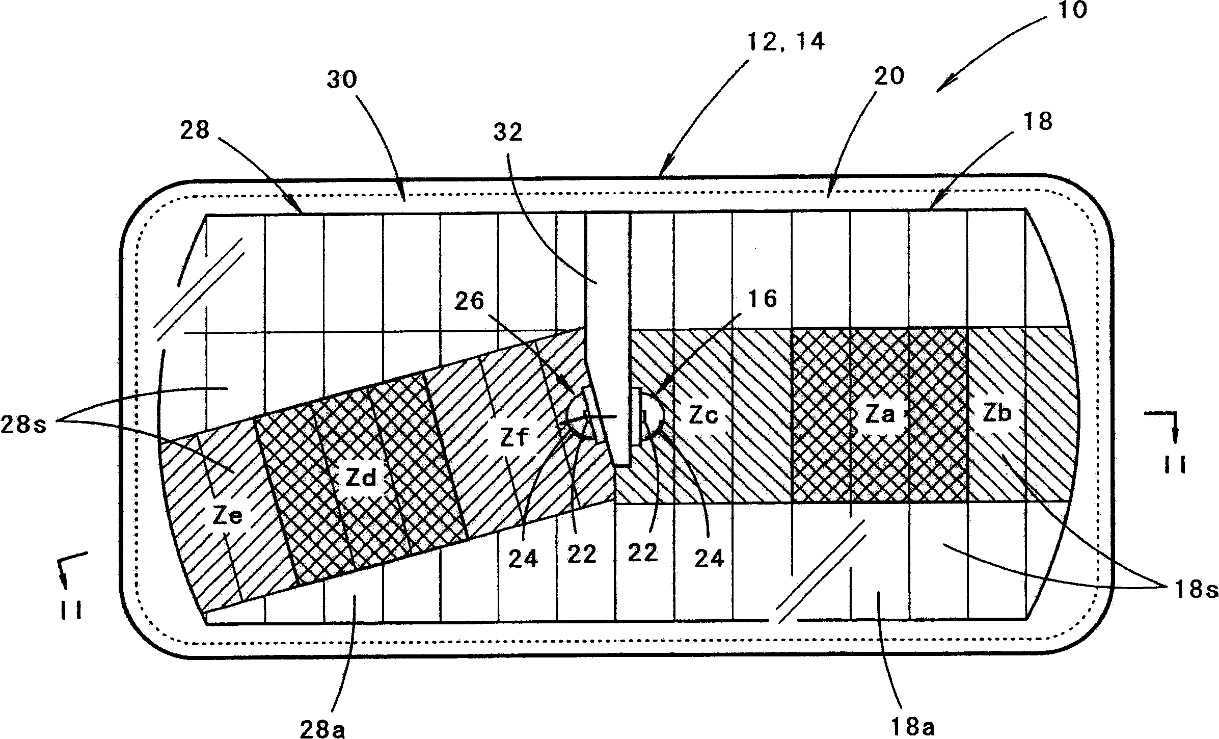
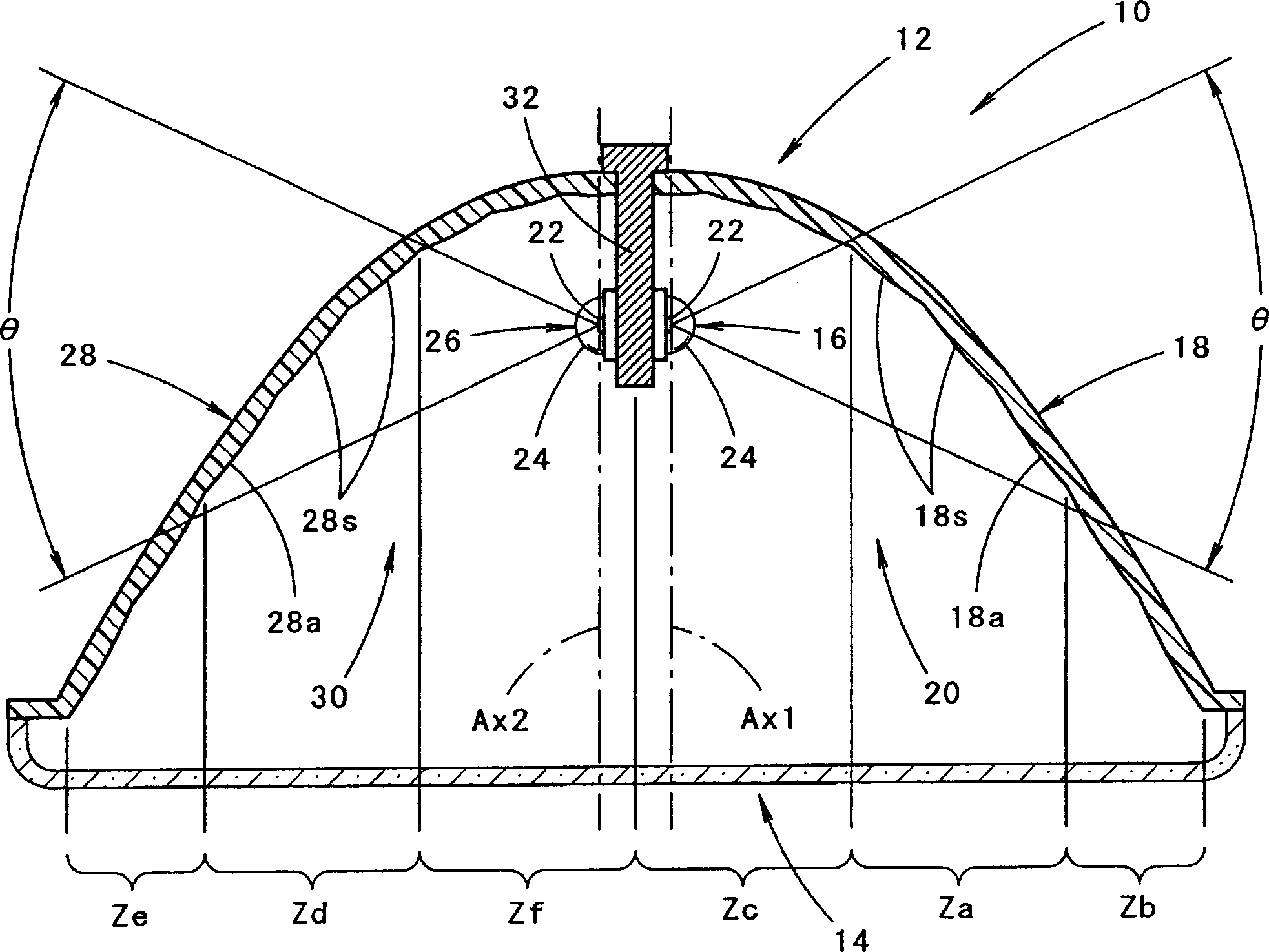
[0032] figure 1 is a front view showing a vehicle headlamp according to an embodiment of the present invention, figure 2 yes means figure 1 The II-II line profile.

[0033] The vehicle headlamp 10 is a lamp configured to form an illumination pattern for low beam, and includes a reflector unit 12 and a transparent translucent cover 14 attached to the front end opening of the reflector unit 12 .

[0034] The reflector unit 12 has a first reflective optical system 20 including a first light source 16 and a first reflector 18 , and a second reflective optical system 30 including a second light source 26 and a second reflector 28 . Both the first and second light sources 16 , 26 are constituted by light emitting diodes formed by covering a rectangular light emitting chip 22 with a hemispherical mold lens 24 , and are supported by a common holder 32 . In addition, the first and...


PUM


Abstract

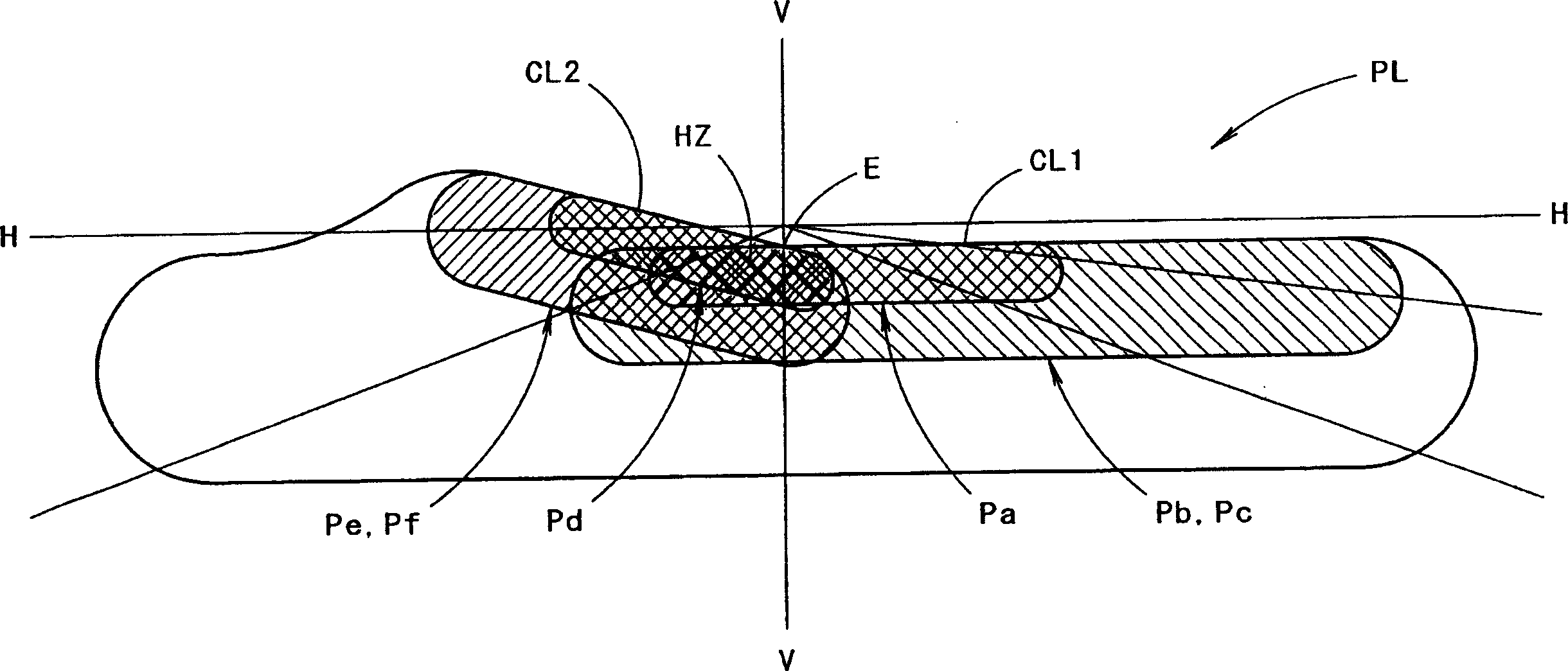
To effectively suppress the generation of glare light in a vehicular headlamp structured so as to form a light distribution pattern having a horizontal cutoff line, by a catoptric system provided with a light source comprising a semiconductor light emitting element. This vehicular headlamp is structured to form the light distribution pattern having the horizontal cutoff line by a first light source 16 comprising a light emitting diode, wherein a rectangular light emitting chip 22 is covered with a hemispherical mold lens 24, and the first catoptric system 20 provided with a first reflector 18 to reflect light toward the front of a lamp from the first light source 16. In this case, the first light source 16 is disposed so as to horizontally turn the light emitting chip 22 with its one side horizontally placed. The horizontal cutoff line is formed by selectively using light reflected by a reflection region Za located in the almost front direction of the light emitting chip 22, out of light from the first light source 16 reflected by the first reflector 18. Thereby, a clear horizontal cutoff line is obtained.

Description

technical field [0001] The present invention relates to a vehicle headlamp configured to form an illumination pattern having a horizontal line by a reflective optical system having a light source composed of a semiconductor light emitting element. Background technique [0002] Conventionally, light-emitting diodes are often used as light sources for vehicle marker lamps such as tail lamps. [0003] For example, "Patent Document 1" describes a vehicle marker lamp in which a plurality of lamp units having light emitting diodes as light sources are arranged. [0004] "Patent Document 1" [0005] Japanese Patent Application Publication No. 2001-332104 [0006] In recent years, due to the development of higher luminance of light emitting diodes, the tendency to adopt the light emitting diodes as light sources of vehicle headlamps has been increasing. [0007] However, many light-emitting diodes, as described in the above-mentioned "Patent Document 1", have a structure in which...

Claims


Application Information

Patent Timeline
Patent Type & Authority Applications(China)
IPC IPC(8): F21S8/12F21S8/10F21V7/00F21V7/09F21V13/00F21W101/10F21Y101/02H01L33/54H01L33/60
CPCF21S48/1159F21S48/1163F21Y2101/02F21S48/1358F21Y2115/10F21S41/148F21S41/155F21S41/334F21S41/337F21S41/20F21S41/36F21W2102/00
Inventor 石田裕之佐塚清
Owner KOITO MFG CO LTD
Learn More