Cooling system for photocosmetic device

A technique for cooling surfaces, skin, applied in the direction of cooling appliances for therapeutic treatments, heating appliances for therapeutic treatments, devices for washing hair or scalp, etc.

Inactive Publication Date: 2004-10-06
PALOMAR MEDICAL TECH
View PDF8 Cites 38 Cited by
  • Summary
  • Abstract
  • Description
  • Claims
  • Application Information

AI Technical Summary

Problems solved by technology

Currently available photocosmetic devices have limitations with respect to one or more of the issues posed above

Method used


Image

  • Cooling system for photocosmetic device
  • Cooling system for photocosmetic device
  • Cooling system for photocosmetic device

Examples


Embodiment Construction

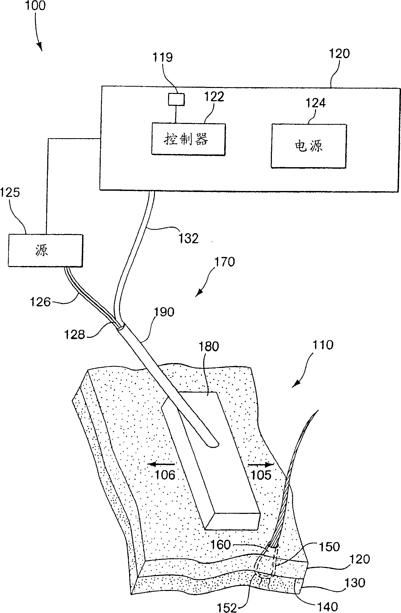
[0068] figure 1 is a schematic illustration of some basic elements of a photocosmetic device according to aspects of the present invention. Area 110 is an area of ​​the patient's skin to be subjected to the selected photocosmetic treatment. The skin area 110 has a base layer 140 between the epidermis 120 and the dermis 130 . Typically, photocosmetic treatments involve treating target areas located within the epidermis 120 or dermis 130 . For example, in the case of hair removal, the bulb 150 of the hair follicle 160 may need to be heated. Additionally, it is possible to heat only a portion of the bulb 150, such as the basement membrane 152 between the mastoid and the capsule.

[0069] In some embodiments of the present invention, the main subsystem of the device 100 includes a handpiece 170 , a base unit 120 and a cord 126 for coupling the handpiece 170 to the base unit 120 . The base unit 120 may include a power supply 124 for powering control electronics 122 and a source...


PUM


Abstract

Photocosmetic device (100) for use in medical or non-medical environments (e.g., a home, barbershop, or spa), which can be used for a variety of tissue treatments. Radiation is delivered to the tissues via optical systems (520 for example) designed to pattern the radiation and project the radiation to a particular depth. The device has a variety of cooling systems including phase change cooling solids and liquids to cool treated skin and the radiation sources (510 for example). Contact sensors (1712) and motion sensor (1820) may be used to enhance treatment. The device may be modular to facilitate manufacture and replacement of parts.

Description

Background of the invention [0001] related application [0002] This application claims priority to Provisional Application Serial No. 60 / 363798, filed March 12,2002. This application is also a continuation-in-part of application serial number 10 / 052,474 filed January 18, 2002 which is a continuation-in-part of application serial number 09 / 473,910 filed December 28, 1999 which is a continuation-in-part of application serial number 09 / 473,910 filed December 28, 1999 Priority is claimed from provisional application serial number 60 / 115,447, filed November 9, 1999, priority is claimed from provisional application serial number 60 / 164,492, filed November 9, 1999, and is filed May 13, 1998, application serial number 09 / 078,055 is a continuation-in-part of what is now U.S. Patent No. 6,273,884, which is a continuation of Provisional Application Serial No. 60 / 046,542 filed May 15, 1997 and Provisional Application Serial No. 60 / 077,726 filed March 12, 1998 Priority claims are made....

Claims


Application Information

Patent Timeline
Patent Type & Authority Applications(China)
IPC IPC(8): A61B18/00A61B17/00A61B18/20A61F7/00A61N5/00A61N5/06
CPCA61B2017/00747A61B2017/00765A45D26/00A61B2018/00636A61B2018/00904A61B2018/00029A61N1/328A61B2018/00011A61B2018/00476A61B18/203A45D26/0061A61B2019/465A61B18/20A61B2017/00769A61B2018/00452A61B2090/065
Inventor G·B·阿尔特舒勒J·D·卡鲁索H·M·岑兹J·布尔克三世A·V·埃夫罗费夫
Owner PALOMAR MEDICAL TECH
Why Eureka
Try Eureka