Base station device and packet transmission method

A technology of base station and modulation mode, applied in the direction of transmission modification based on link quality, transmission system, adjustment of transmission rate, etc., can solve problems such as no public scheduling technology

Inactive Publication Date: 2004-10-13
PANASONIC CORP
View PDF1 Cites 45 Cited by
  • Summary
  • Abstract
  • Description
  • Claims
  • Application Information

AI Technical Summary

Problems solved by technology

[0008] However, there is no known scheduling technology that can determine the most suitable combination of modulation scheme and error correction coding scheme according to the service level of the transmitted packet

Method used


Image

  • Base station device and packet transmission method
  • Base station device and packet transmission method
  • Base station device and packet transmission method

Examples


Embodiment 1

[0021] In Embodiment 1 of the present invention, in '(b) the communication terminal device estimates or estimates the quality of the downlink and reports it to the base station device, and the base station device sets the most suitable transmission format according to the reported value ( That is, a method of "modulation scheme and error correction coding scheme"), and a case where a combination of a modulation scheme and an error correction coding scheme suitable for each service class is determined will be described. In addition, in this embodiment, it is assumed that radio resources are allocated by the maximum C / I method.

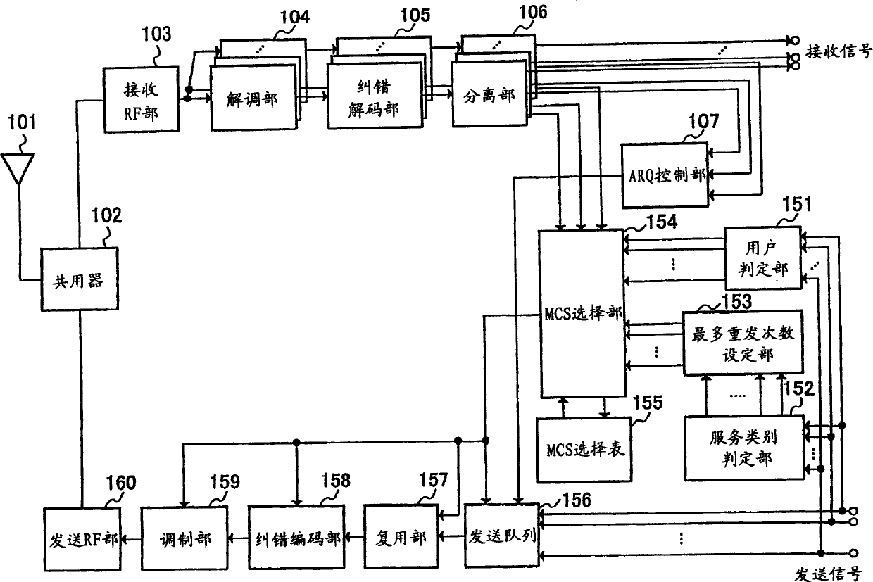
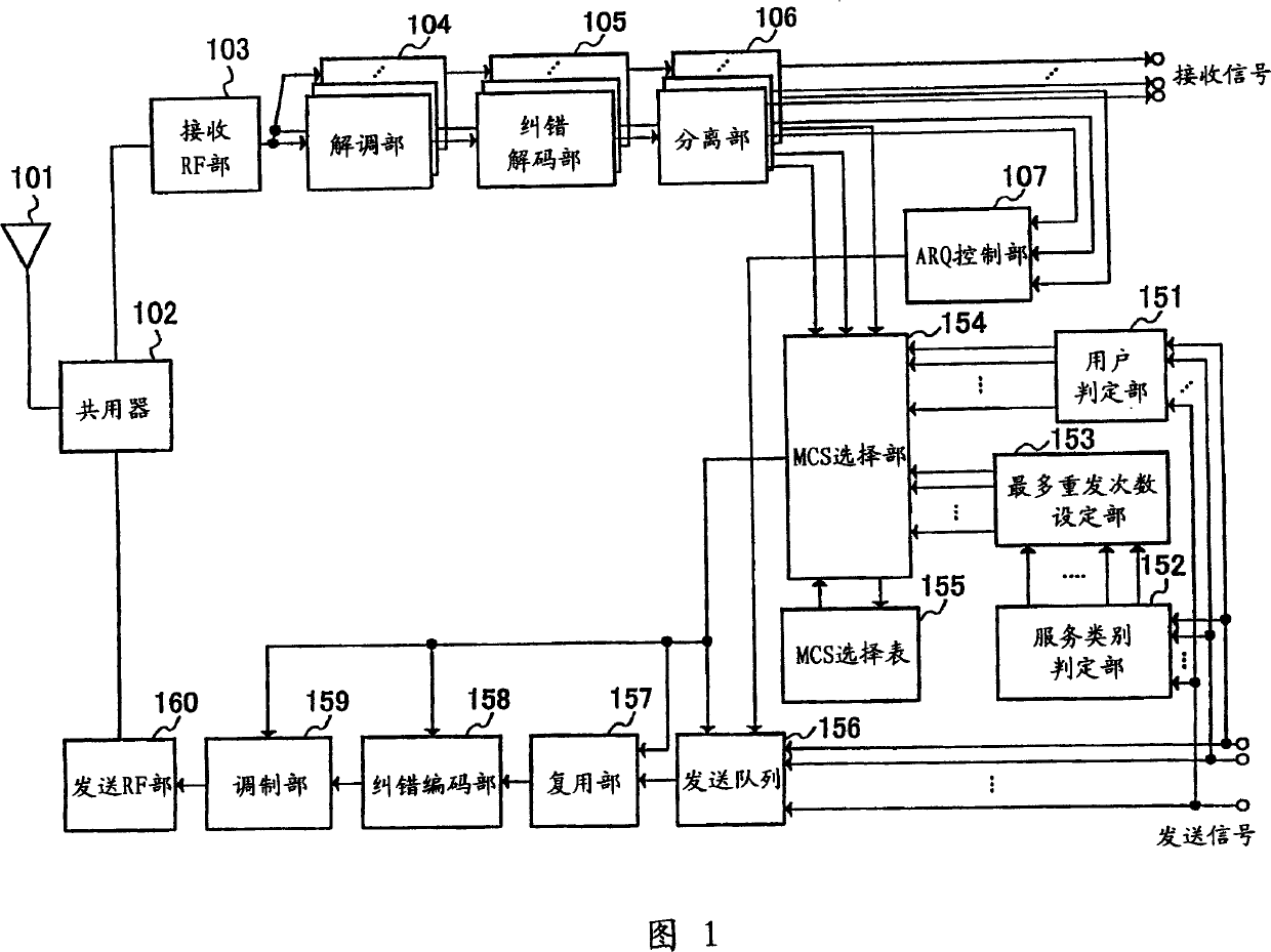
[0022] Fig. 1 is a block diagram showing the configuration of a base station apparatus according to Embodiment 1 of the present invention. In Figure 1, the base station device has:

[0023] An antenna 101 , a duplexer 102 , a receiving RF unit 103 , a demodulation unit 104 , an error correction decoding unit 105 , a separation unit 106 , and an ARQ con...

Embodiment 2

[0043] In Embodiment 2 of the present invention, regarding the method of setting an appropriate transmission format (i.e. modulation method and error correction coding method) by the base station device without receiving a report from the communication terminal device in (c)", it is determined The combination of the modulation scheme and the error correction coding scheme most suitable for each service class will be described.

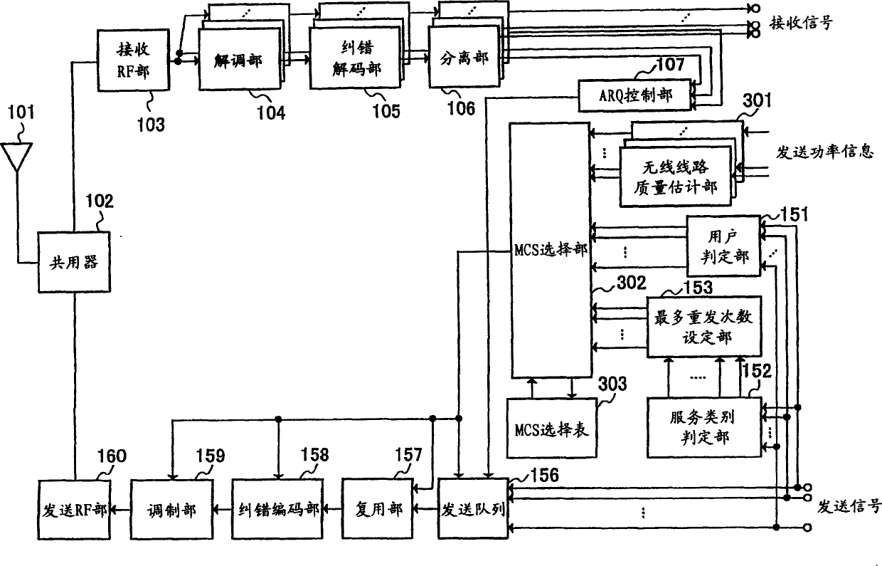
[0044] Fig. 3 is a block diagram showing the configuration of a base station apparatus according to Embodiment 2 of the present invention. In addition, in the base station apparatus in FIG. 3, the same components as those in FIG. 1 are given the same symbols as those in FIG. 1, and detailed description thereof will be omitted.

[0045] The base station apparatus in FIG. 3 has a configuration in which a radio channel quality estimating unit 301 is added to that in FIG. 1 . Furthermore, in the base station apparatus of FIG. 3 , the role of MCS selection...


PUM


Abstract

A service kind determining section 152 determines a service class from service information included in the header of transmission data of each communication terminal apparatus. A maximum retransmission number setting section 153 sets the maximum number of retransmissions from an allowable delay time allowed in each service class. An MCS selecting section 154 decides a communication terminal apparatus that transmits a packet based on a report value from each communication terminal apparatus, and outputs information indicating the destination apparatus to a transmission queue 156 with reference to a determination result of a user determining section 151. Moreover, the MCS selecting section 154 selects a suitable modulation system and a coding rate from the MCS selection table 154 based on the maximum number of retransmissions of the destination apparatus and the report value, and outputs information indicating the selected modulation system and coding rate to a multiplexing section 157, an error correction coding section 158 and a modulating section 159. This makes it possible to decide an optimal combination of the modulation system and the error correction coding system.

Description

technical field [0001] The invention relates to a base station device and a packet transmission method for downlink high-speed packet transmission. Background technique [0002] Currently, a downlink high-speed packet transmission method (HSDPA, etc.) has been developed in which a plurality of communication terminal devices share a high-speed and large-capacity downlink channel to perform high-speed packet transmission. In this transmission method, scheduling technology and adaptive modulation technology are used to improve transmission efficiency. [0003] The so-called scheduling technique is a technique in which a base station apparatus allocates communication terminal apparatuses to which downlink high-speed packets are to be transmitted. Typical scheduling techniques in the past include the 'Maximum C / I (Carrier to Interference) method' in which each communication terminal device observes the state of the downlink propagation path and assigns priority to users with the...

Claims


Application Information

Patent Timeline
Patent Type & Authority Applications(China)
IPC IPC(8): H04L1/16H04B7/26H04L1/00H04L1/18
CPCH04L1/0009H04L1/0003H04L1/1812
Inventor 平松胜彦
Owner PANASONIC CORP
Why Eureka
Try Eureka