Method for guiding plate link chainsin area of reversing devices of pedestrian conveyor system

A technology of conveying system and rotary device, applied in transportation and packaging, escalators, etc., can solve the problem of polygon and rotary effect difficult to control, and achieve the effect of reducing polygon effect, excellent running characteristics, and quiet running enhancement.

Inactive Publication Date: 2004-10-20
KONE CORP
View PDF3 Cites 6 Cited by
  • Summary
  • Abstract
  • Description
  • Claims
  • Application Information

AI Technical Summary

Problems solved by technology

Without these methods above, it will be difficult to control the polygon and rotation effects

Method used


Image

  • Method for guiding plate link chainsin area of reversing devices of pedestrian conveyor system
  • Method for guiding plate link chainsin area of reversing devices of pedestrian conveyor system

Examples


Embodiment Construction

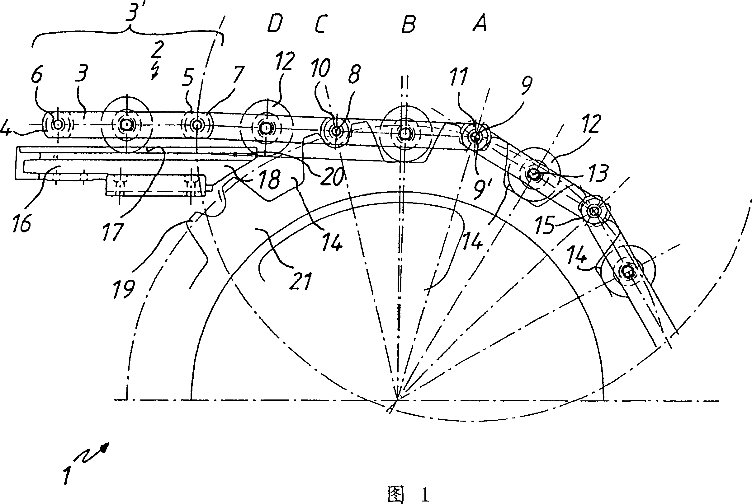
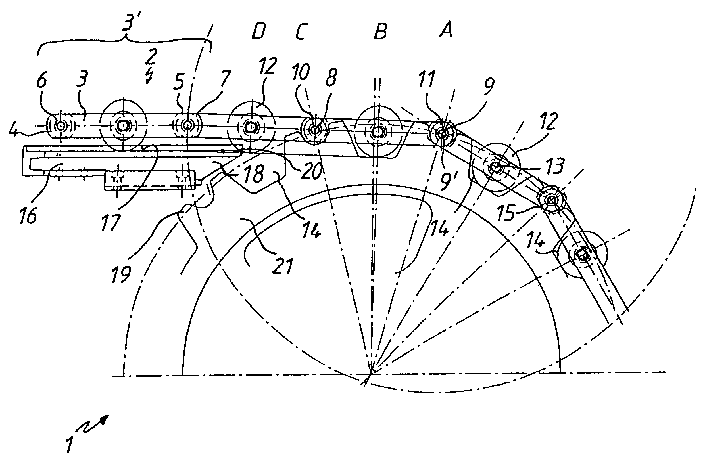
[0015] The schematic diagram illustrates the swivel area 1 of the slat chain 2 . Therein, the link link chain 2 comprises individual link links 3 guided in parallel in an interacting relationship with one another in their connection regions via connecting elements 6, 7, forming link link elements 3'. The connecting elements 6 , 7 are formed by pins 8 , 9 and guide bushes 10 , 11 . Between the connecting regions 4 , 5 of the individual parallel chain plates 3 , at approximately half-height, guide rollers 12 are arranged, rotatable about axes 13 . If possible, without generating polygonal and turning effects, the chain link chain 2 turns around a chain wheel 21 arranged therein, for example, in the turning region 1 of an escalator or a moving walk (not shown further). The sprocket 21 is provided with a circular seat 14 for receiving the guide roller 12 . Between the circular seats 14 , an engagement zone 15 is provided for receiving and guiding the connection elements 6 , 7 ie...


PUM


Abstract

The invention relates to a method for guiding a drive chain containing links, guide rolls and connecting elements in the area of a reversing device, which is formed by a chain wheel, of a pedestrian conveyor system, particularly of an escalator or a moving sidewalk, whereby the guide rolls are supported, at least on the chain wheel side, on a guide profile. In drive chains of this type, which have connecting elements in the coupling areas of the links and in which a guide roll mounted between the links is provided in the remaining free space, the drive chain is led into the chain wheel such that when viewed in a moving direction the front connecting element of each link element is firstly placed in an associated accommodating area and the guide roll is subsequently placed in a corresponding calotte, and the rear connecting element is firstly led into the associated accommodating area when the guide roll is supported in the calotte in an elastically damped manner.

Description

technical field [0001] The invention relates to a method for guiding a drive chain consisting of chain plates, guide rollers and connecting elements in the region of a slewing device consisting of sprockets of a pedestrian conveyor system, in particular an escalator or a moving walkway, wherein the guide The roller is supported on the guide profile at least on the sprocket side. Background technique [0002] During the slewing of the pedestrian conveyor drive chain through the slewing device including the sprockets, undesired polygonal and slewing effects occur which adversely affect the quiet operation of the pedestrian conveyor. The polygon effect is caused by the chain polygons being supported on the sprockets. As the angle of rotation increases, the effective radius of the sprocket changes, so the speed of the chain fluctuates between maximum and minimum values. The chain rollers and sprocket teeth have different speeds when meshing with the sprocket, thus causing coll...

Claims


Application Information

Patent Timeline
Patent Type & Authority Applications(China)
IPC IPC(8): B66B23/02
CPCB66B23/02B66B23/026
Inventor 亚历山大·皮茨
Owner KONE CORP
Why Eureka
Try Eureka