
Internal voltage generating apparatus adaptive to temperature change

a voltage generation apparatus and temperature technology, applied in the direction of electric variable regulation, process and machine control, instruments, etc., can solve the problems of high current dissipation, /b> being considered the most critical disadvantage, and no known method of compensating temperature characteristics, etc., to improve the operation characteristic of a semiconductor device and increase the reliability of the semiconductor device.

Active Publication Date: 2008-09-02
SK HYNIX INC
View PDF11 Cites 11 Cited by
  • Summary
  • Abstract
  • Description
  • Claims
  • Application Information

AI Technical Summary

Benefits of technology

"The present invention provides an internal voltage generating apparatus that can adjust the temperature characteristic of a semiconductor device and improve its operation and reliability. The apparatus includes a complementary to absolute temperature (CTAT) type transistor and a proportional to absolute temperature (PTAT) type transistor for generating initial reference voltage signals. A buffer circuit then generates reference voltage signals based on these signals and an internal voltage generating circuit generates an internal voltage signal using the reference voltage signals and an inputted power voltage."

Problems solved by technology

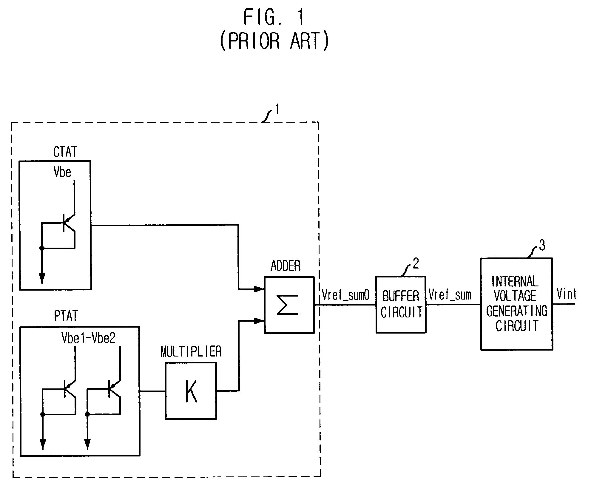
However, according to the conventional reference voltage generating circuit, when the above driver exhibits a temperature characteristic due to device or process characteristics, there is no known method of compensating the temperature characteristic.
Especially, the second reference voltage signal Vref—sum supplied to the gate of the second NMOS transistor N3 is considered the most critical disadvantage.
If the driver has the positive temperature characteristic, the driver has an increased responsiveness at low temperature, which results in high current dissipation, whereas the driver has a decreased responsiveness at high temperature, which decreases the current dissipation.
In some cases, the current dissipation related to the response may become a direct cause of failures.

Method used


Image

  • Internal voltage generating apparatus adaptive to temperature change
  • Internal voltage generating apparatus adaptive to temperature change
  • Internal voltage generating apparatus adaptive to temperature change

Examples


Embodiment Construction

[0028]An internal voltage generating apparatus adaptive to a temperature change in accordance with exemplary embodiments of the present invention will be described in detail with reference to the accompanying drawings.

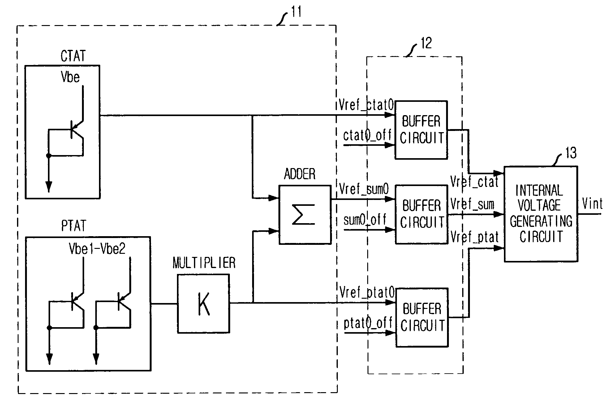
[0029]FIG. 5 is a block diagram of an internal voltage generating apparatus operating in a down-conversion mode in accordance with an embodiment of the present invention. Particularly, FIG. 5 illustrates the concept of the internal voltage generating apparatus according to this embodiment of the present invention.

[0030]The internal voltage generating apparatus includes a reference voltage circuit 11, a buffer circuit 12, and an internal voltage generating circuit 13.

[0031]This embodiment of the present invention is distinctive from the conventional internal voltage generating apparatus in that a first initial reference voltage signal Vref—ctat0 outputted from a complementary to absolute temperature (CTAT) bipolar junction transistor (BJT) and a second initial reference...


PUM


Abstract

An internal voltage generating apparatus adaptive to a temperature change includes a reference voltage circuit including a complementary to absolute temperature (CTAT) type transistor and a proportional to absolute temperature (PTAT) type transistor for generating a first to a third initial reference voltage signals. A buffer circuit for buffering a first, a second and a third initial reference voltage signal is included to generate a first, a second, and a third reference voltage signal in response to enable signals. An internal voltage generating circuit is included to generate an internal voltage signal based on the first, the second and the third reference voltage signal by using an inputted power voltage.

Description

FIELD OF THE INVENTION[0001]The present invention relates to an internal voltage generating apparatus and in particular to an internal voltage generating apparatus capable of controlling various responses to a temperature change.DESCRIPTION OF THE RELATED ART[0002]Generally, a method of generating an internal voltage through converting an external voltage (e.g., a power supply voltage VDD), which is supplied from an external circuit, into a low voltage level and driving current internally consumed during standby and activation operations using the internal voltage has been employed to meet the demands of high-speed operation and low power dissipation required for dynamic random access memory (DRAM) devices. In addition to the aforementioned memory devices, the above method of generating the internal voltage using the external voltage has been applied to other types of semiconductor devices.[0003]The internal voltage is generated through a down-conversion operation with respect to th...

Claims


Application Information

Patent Timeline
Patent Type & Authority Patents(United States)
IPC IPC(8): G05F3/16G05F1/10
CPCG05F3/30G05F1/465
Inventor BYEON, SANG-JINYOON, SEOK-CHEOL
Owner SK HYNIX INC
Learn More