Self-contained compression brakecontrol module for compression-release brakesystem of internal combustion engine

a technology of internal combustion engine and control module, which is applied in the direction of machines/engines, output power, non-mechanical valves, etc., can solve the problems of engine braking, engine retardation, engine blow-down of compressed cylinder gas, etc., to reduce engineering and component cost, reduce engine braking, and compact

Inactive Publication Date: 2011-03-08
PACBRAKE
View PDF24 Cites 12 Cited by
  • Summary
  • Abstract
  • Description
  • Claims
  • Application Information

AI Technical Summary

Benefits of technology

[0013]According to a first exemplary embodiment of the present invention, the CBCM is hydraulically actuated and the compression-release brake system further comprises an external control valve to supply the pressurized hydraulic fluid to the CBCM during the compression-release engine braking operation. To deactivate the compression-release brake system, the external control valve dumps the pressurized hydraulic fluid to a hydraulic fluid sump. With the hydraulic controlled CBCM, the slave piston chamber is completely filled with the hydraulic fluid during the normal exhaust stroke when the exhaust valve is lifted off its valve seat by the normal exhaust cam profile. The hydraulic fluid in the slave piston chamber is hydraulically locked by the check valve located above the slave piston to hold the slave piston in the extended position. At the completion of the normal exhaust valve motion, the extended slave piston stops the exhaust valve from returning to the valve seat and thereby holds the exhaust valve open.
[0019]Therefore, a compression-release brake system in accordance with the present invention with a self-contained compression brake control module improves and optimizes operational characteristics of the internal combustion engine and provides small compact and universal design, allows for individual cylinder application and component flexibility, requires minimum fluid compliance, lowers engineering and component cost, and reduces development time.

Problems solved by technology

This creates a blow-down of the compressed cylinder gas and the energy used for compression is not reclaimed.
The result is engine braking, or retarding, power.
A conventional compression-release engine brake system has substantial cost associated with the hardware required to open the exhaust valve(s) against the extremely high load of a compressed cylinder charge.
Also, the sudden release of the highly compressed gas comes with a high level of noise.
In some areas, engine brake use is not permitted because the existing compression-release engine brake systems open the valves quickly at high compression pressure near the TDC compression that produces high engine valve train loads and a loud sound, which has resulted in prohibition of engine compression release brake usage in certain urban areas.
Accordingly, both the development time and cost have been an area of concern.
The restriction is simply insufficient to be effective at the lower engine speeds.
While known compression-release engine brake systems have proven to be acceptable for various vehicular driveline applications, such devices are nevertheless susceptible to improvements that may enhance their performance and cost.

Method used


Image

  • Self-contained compression brakecontrol module for compression-release brakesystem of internal combustion engine
  • Self-contained compression brakecontrol module for compression-release brakesystem of internal combustion engine
  • Self-contained compression brakecontrol module for compression-release brakesystem of internal combustion engine

Examples


Embodiment Construction

[0036]The preferred embodiments of the present invention will now be described with the reference to accompanying drawings.

[0037]For purposes of the following description, certain terminology is used in the following description for convenience only and is not limiting. The words such as “front” and “rear”, “left” and “right”, “inwardly” and “outwardly” designate directions in the drawings to which reference is made. The words “smaller” and “larger” refer to relative size of elements of the apparatus of the present invention and designated portions thereof. The terminology includes the words specifically mentioned above, derivatives thereof and words of similar import.

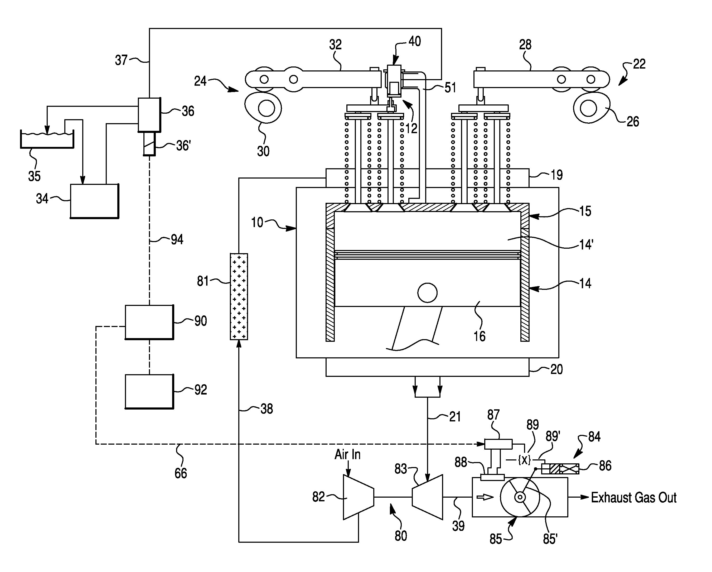
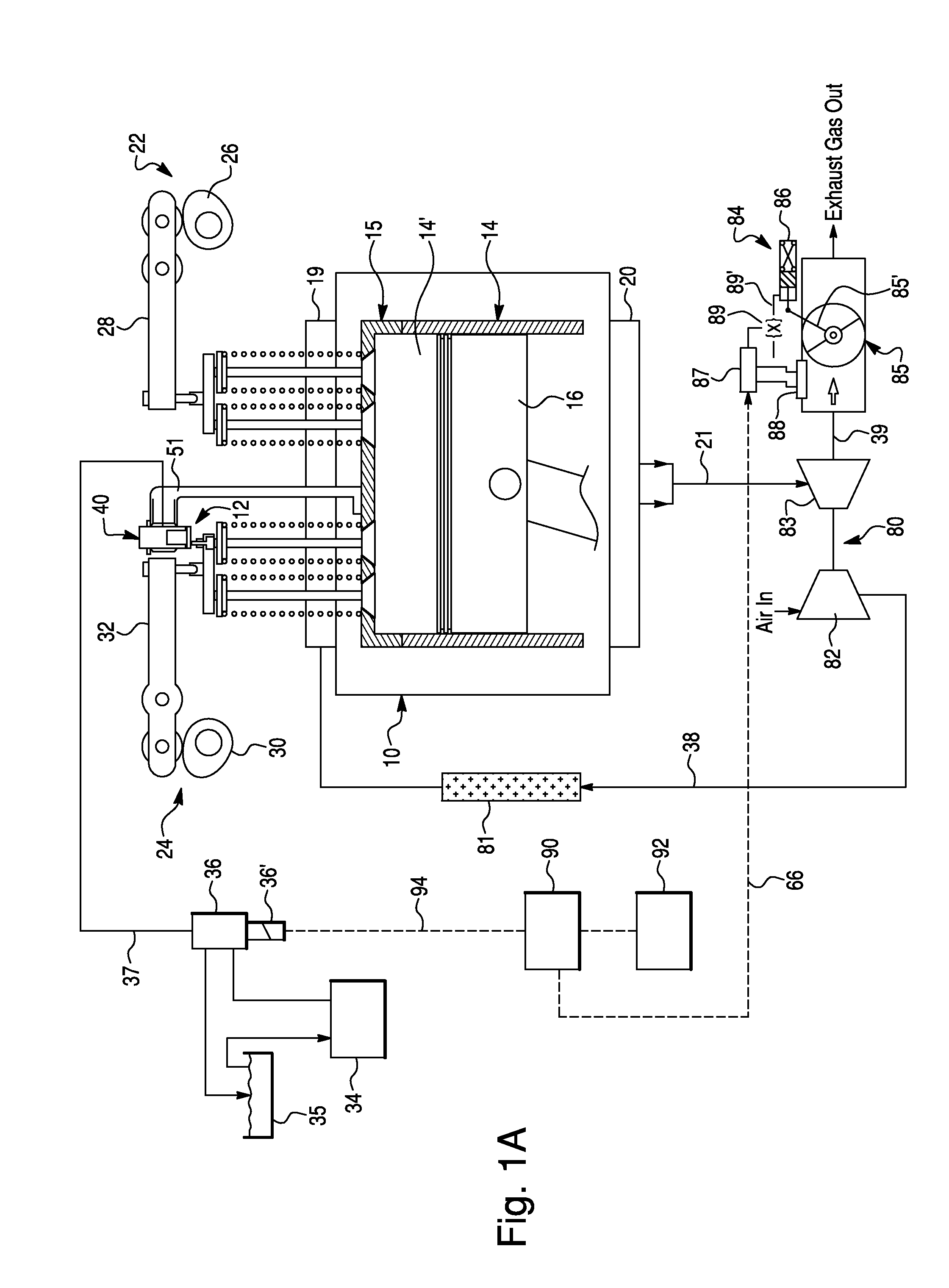
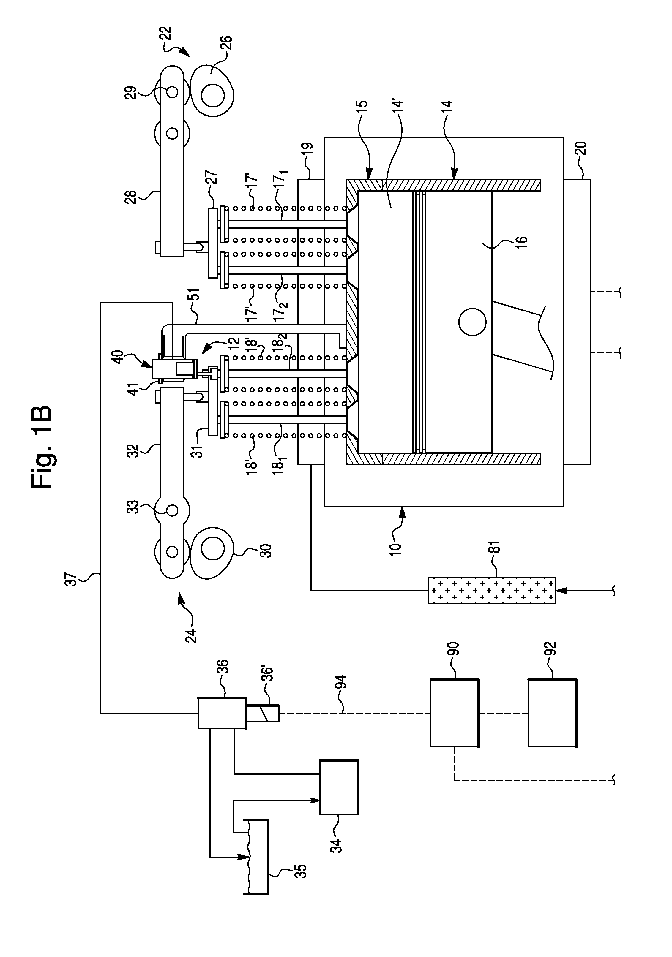
[0038]FIG. 1 schematically depicts a compression-release (or weeper) brake system 12 according to a first exemplary embodiment of the present invention, provided for an internal combustion (IC) engine 10. Preferably, the IC engine 10 is a four-stroke diesel engine, comprising a cylinder block 14 including a plurality o...


PUM


Abstract

A compression-release brake system for operating an exhaust valve of an engine during an engine braking operation. The compression-release brake system comprises a self-contained compression brake control module (CBCM) operatively coupled to the exhaust valve for controlling a lift and a phase angle thereof and a source of a pressurized hydraulic fluid. The CBCM includes a casing defining piston and actuator cavities, a slave piston mounted within the piston cavity, a check valve provided between a supply conduit and a slave piston chamber and a compression brake actuator disposed in the actuator cavity. The compression brake actuator includes an actuator element and a biasing spring. The actuator element selectively engages the check valve when deactivated so as to unlock the slave piston chamber, and disengages from the check valve when activated so as to lock the slave piston chamber. The actuator element is exposed to atmospheric pressure.

Description

CROSS-REFERENCE TO RELATED APPLICATION[0001]This Application claims the benefit under 35 U.S.C. 119(e) of U.S. Provisional Application No. 61 / 085,110 filed Jul. 31, 2008 by Meneely, V. et al.BACKGROUND OF THE INVENTION[0002]1. Field of the Invention[0003]The present invention relates to compression-release brake systems for internal combustion engines in general, and, more particularly, to a self-contained compression-release brake control module for a compression-release engine brake system of an internal combustion engine.[0004]2. Description of the Prior Art[0005]For internal combustion engines (IC engine), especially diesel engines of large trucks, engine braking is an important feature for enhanced vehicle safety. Consequently, the diesel engines in vehicles, particularly large trucks, are commonly equipped with compression-release engine brake systems (or compression-release retarders) for retarding the engine (thus, vehicle). The compression release engine braking provides si...

Claims


Application Information

Patent Timeline
Patent Type & Authority Patents(United States)
IPC IPC(8): F02D9/06
CPCF01L13/065F02D9/06F02D13/04
Inventor MENEELY, VINCENTPRICE, ROBERT
Owner PACBRAKE
Why Eureka
Try Eureka